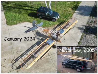

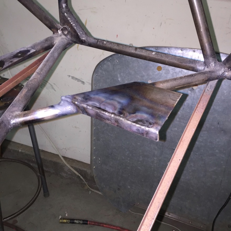
Another catch up post. This next step started in one direction and went a totally different way. I started out this step working on a pattern for the plywood floor in the forward most section of the fuselage. As I started, I decided to make some changes to the mounting pad for the rudder bar. That led into establishing the locations of fairleads and an additional pulley to guide the rudder cables. A snow ball effect started from there. First, the beginnings of the floor pattern. Right off the bat I realized I needed to raise the center pad for the rudder bar. The existing pad was below the level of the floor. Simple enough: remove, redesign, fabricate, and weld in place.
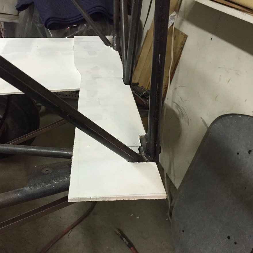
I started the floor pattern using pieces of 1/4” white foam board. I used sections so I could cut around the tubes and other issues in the way. I also didn’t have all the floor tabs welded in yet so not everything could be located. First parts cut and fitted together.
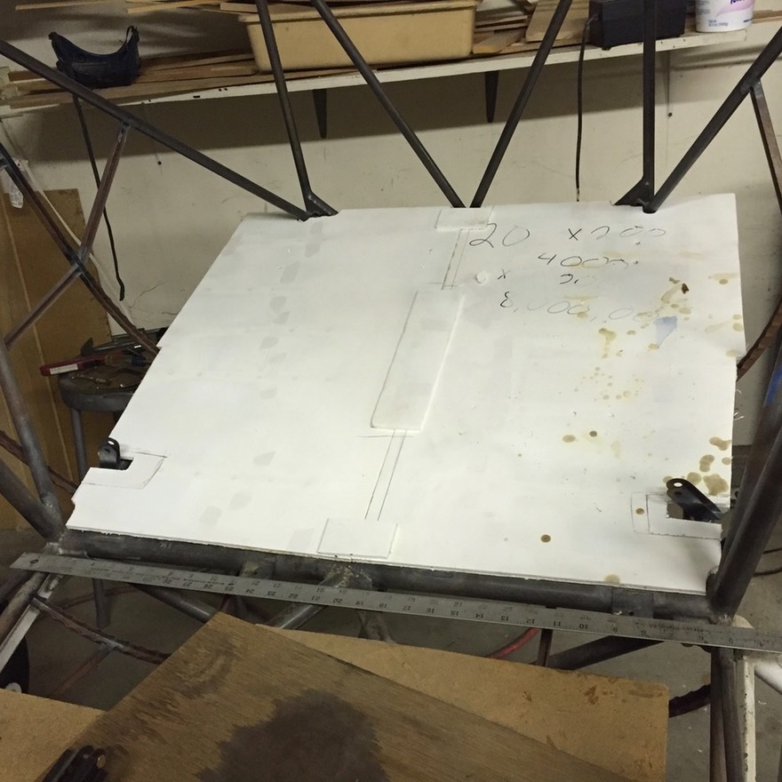
Here’s the first pattern without the cut outs for the rudder or sticks.
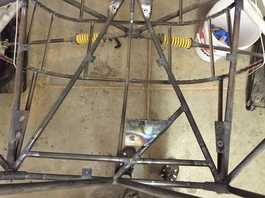
Next, I needed to mount the rudder bar. Right away, I noticed that the drawings in the plans did not have a cut out for the “V” on the rudder bar. I realized I did not make my rudder bar as per the plans. I did some research and realized I made my rudder bar matching a PA20/22 where the “V” goes through the floor. On the 2+2, the “V” does not go through the floor. I can’t figure out how the 2+2 version works. Anyway, I decided to stick with the PA20/22 design and move forward. The next picture shows the rudder bar mounted and a hole cut into the floor pattern for the “V”.
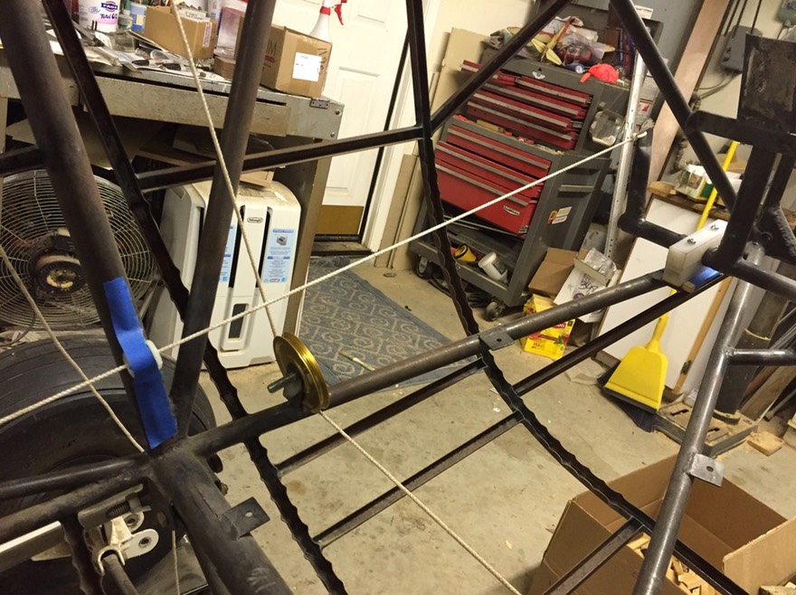
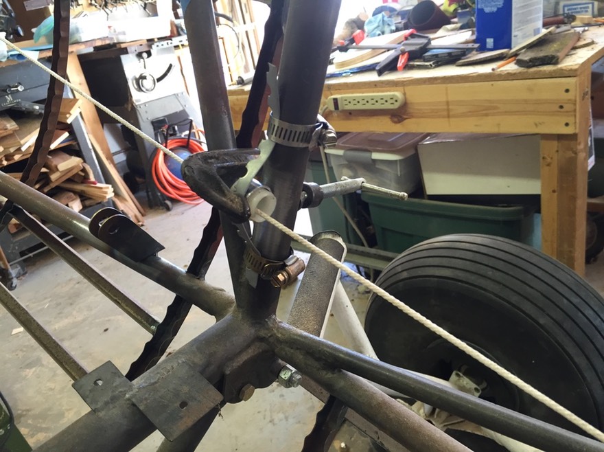
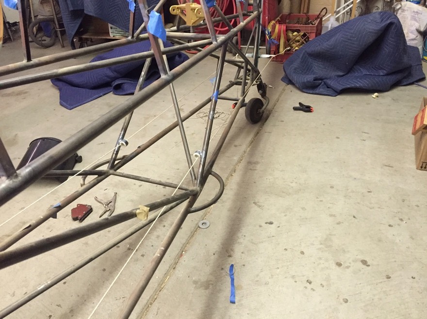
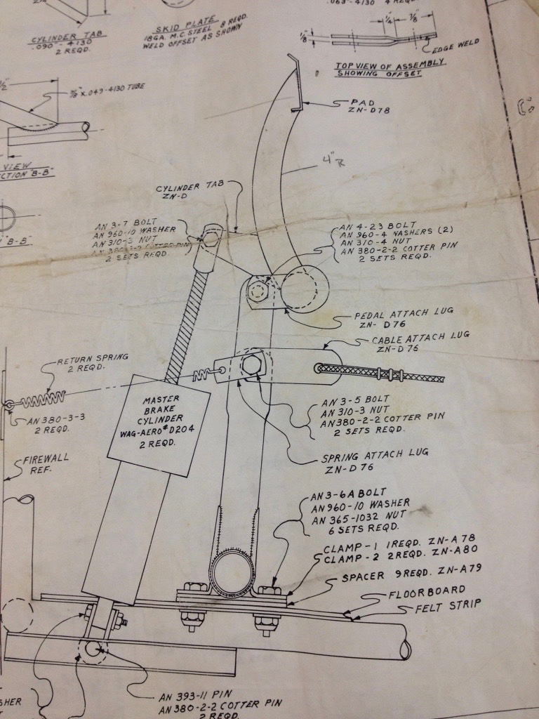
Next, I started fabricating the rudder pedals and attachment fittings for the brake master cylinders. I won’t go into a lot of detail because after completion, I did not like the pedals at all. I did use these pedals to run the cable along the side of the fuselage for the fairleads and a pulley at the door. This next picture shows a temporary cable to locate the fairlead.
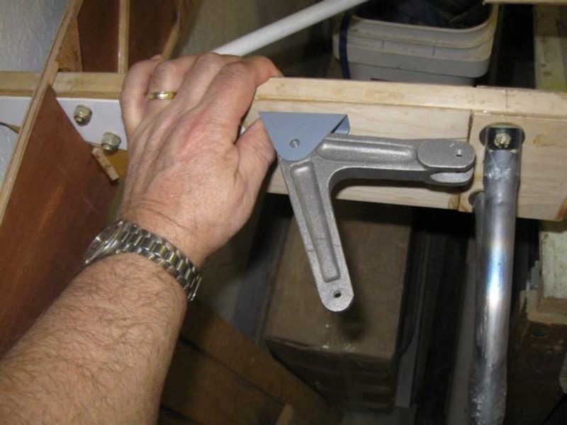
I determined the location for a pulley along the door opening. You can see how much the angle of the cable needs to change here. I am using a small pulley to make this angle change.
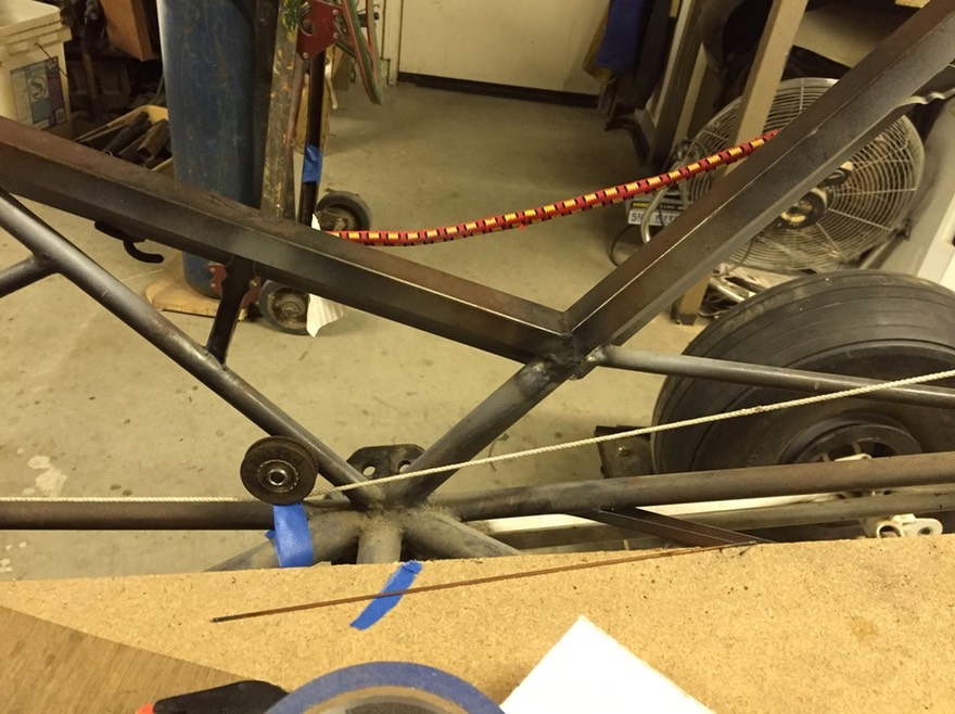
Continuing along the side, other fairlead locations were determined and located with taped fairleads.
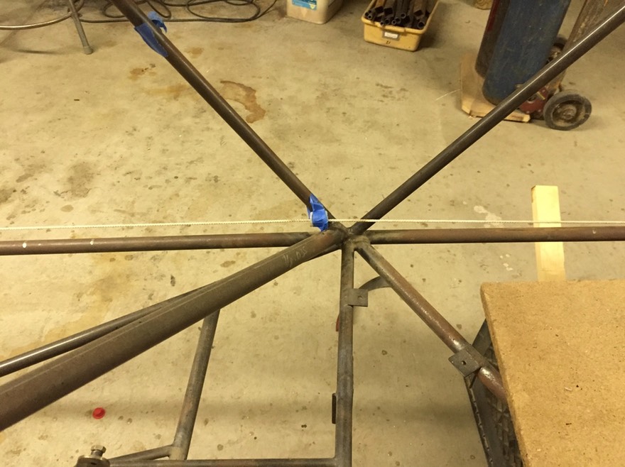
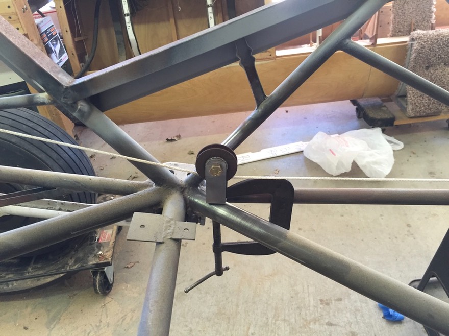
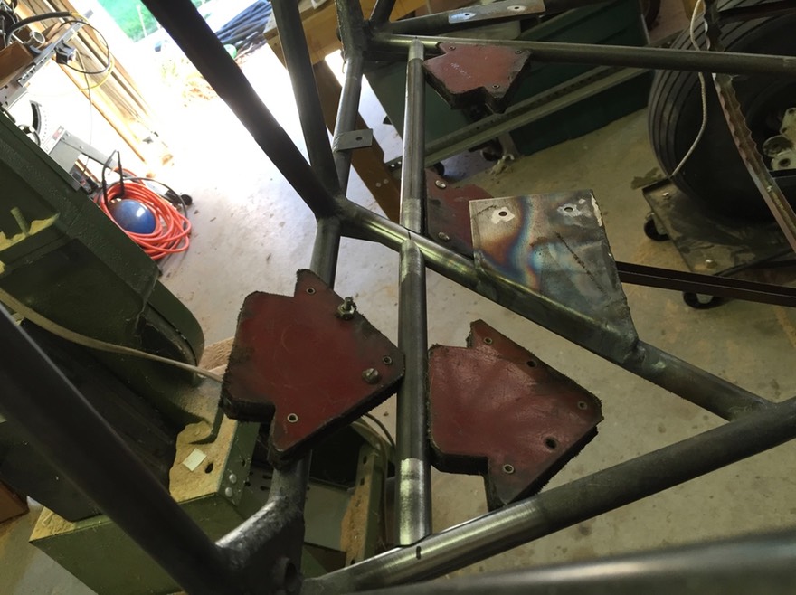
Below you can see some of the rough locations and jigs needed to hold the pulleys and fairleads in place for welding.
The pulley next to the door ……….
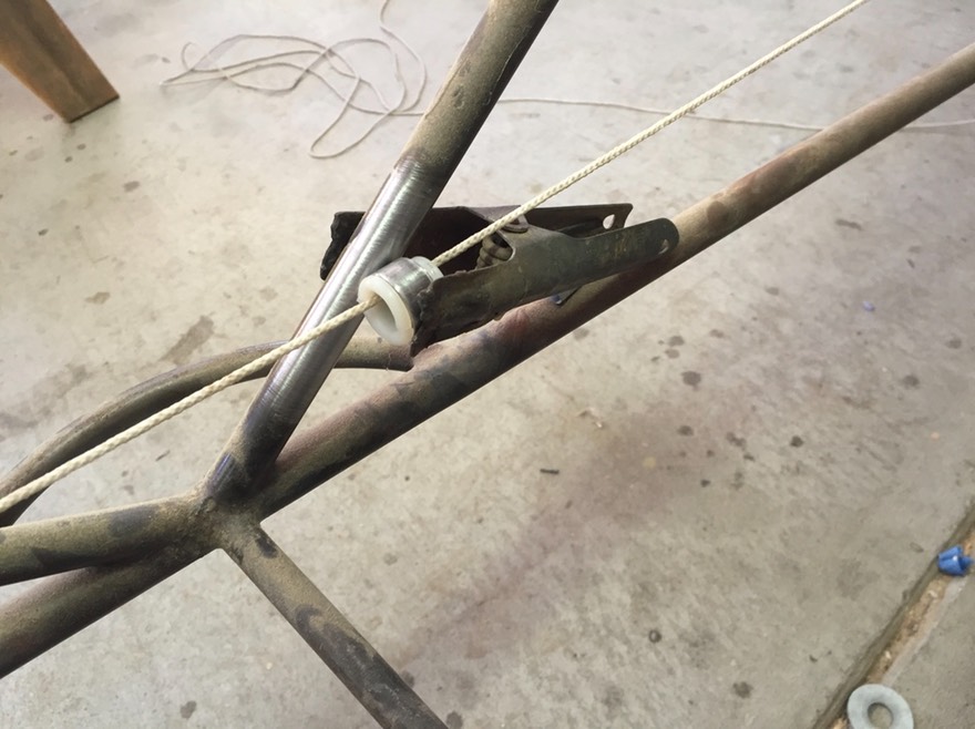
Another fairlead along the side of the fuselage. This is a standard 7/8” tube to hold the fairlead and lock ring inlace.
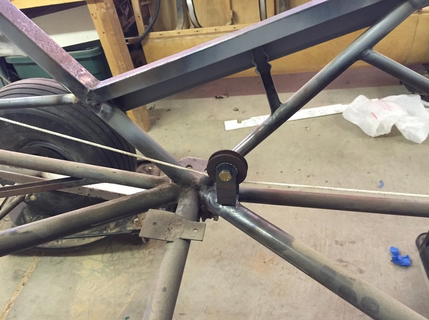
Pulley bracket and fairleads tack welded in place.
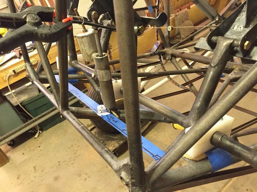
Back to the rudder bar. I needed to add the mounting tabs for the ends of the brake master cylinders. I didn’t particularly like the mounts in the plans So I had to came up with my own design. The blue tape shows the locations based on the master cylinders I had on hand. These are the same size as called out in the plans so I was able to use these for this mock up.
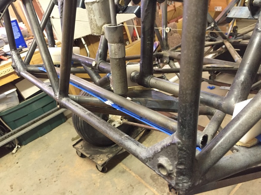
I first needed to weld in a 5/8” tube that I would use to attach the ends of the master cylinders. The next couple of pictures shows that progression.
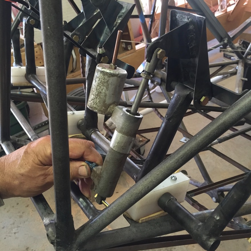
This is about when I realized I didn’t like the way the pedals worked. The height and general feel did not appeal to me. This next shot shows the pedal as I was figuring out how to connect the master cylinder to the new tube.
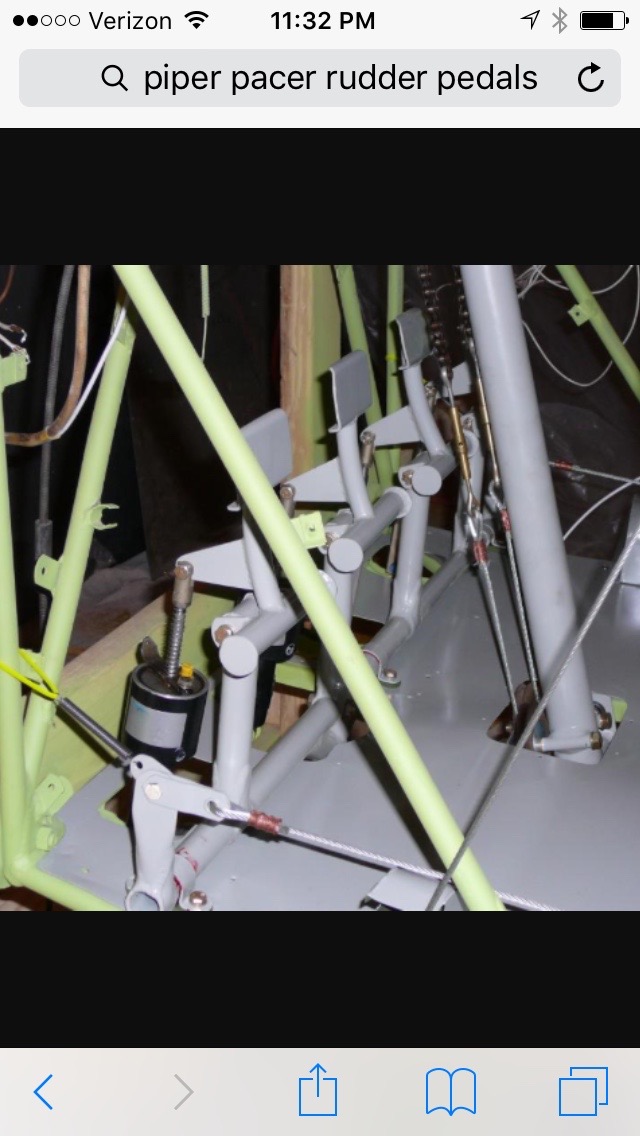
I found a picture of a set of Piper pedals that I liked and decided to toss what I had made and start over on the pedals. Sure glad the pedals are removable from the rudder bar! Here’s what I found that I liked:
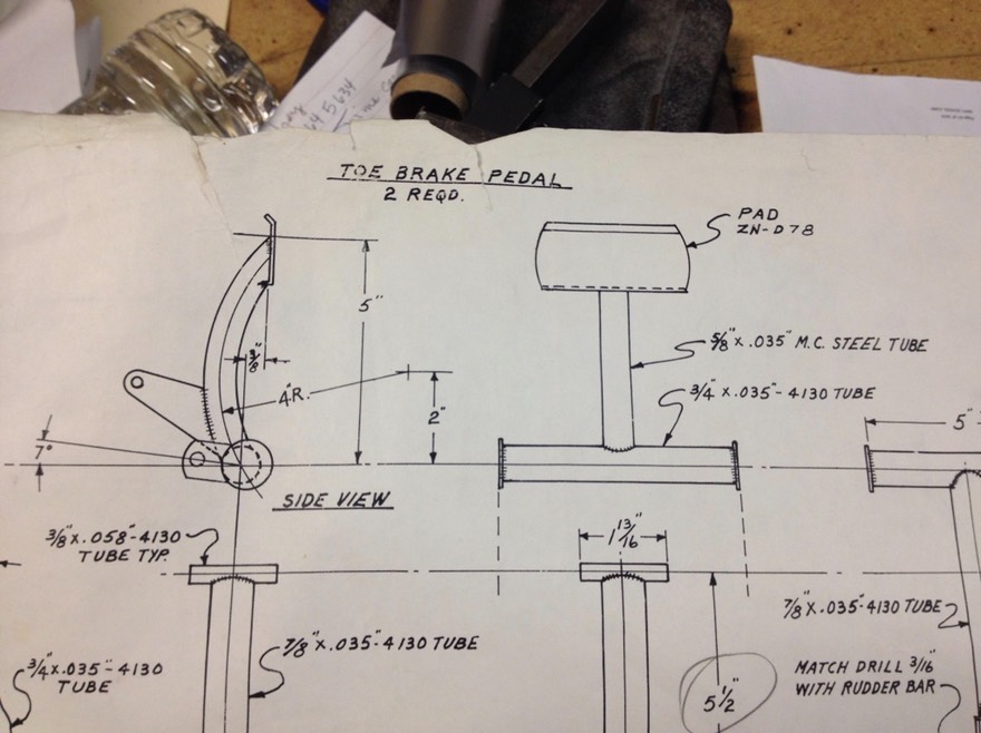
I located some drawings of the Piper pedals and started fabricating new pedals. I had about 20+ hours in the first set of pedals. Oh well ………
Next post will be fabricating the new pedals.