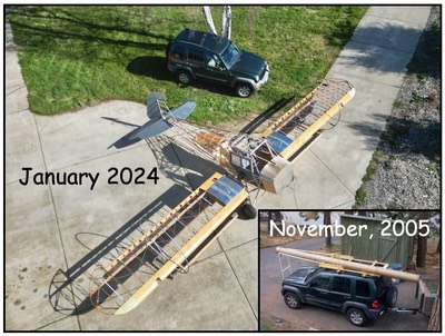
Since my last post in April, after Sun-N-Fun, I worked the Great Alaskan Aviation Gathering in Anchorage in May, the West Coast Cub Fly In in Lompoc, California in early July followed by Airventure in Oshkosh. I also am helping with a fabric re-cover of a T-Craft here in California and have another Stewart Systems seminar this coming weekend. Yes, I have been busy.
Engine Mount Nightmare
To help with the time issues, I decided in July to forgo building my own engine mount (next step) and bought a factory mount …… big mistake. WARNING …… buy an engine mount before welding up the mounting lugs on your fuselage so everything will fit!!! I didn’t do that and ran into all sorts of issues.
Here’s what happened. First, I had gotten advice that the engine mount was flexible to a degree, like that on a Super Cub. So, my mount lugs were close; close enough I thought. Turned out, the PA12 and PA14 engine mount have an “X” brace at the base where a PA18 has a “Y” brace. The “Y” is flexible and the “X” is not, so my factory mount would not fit.
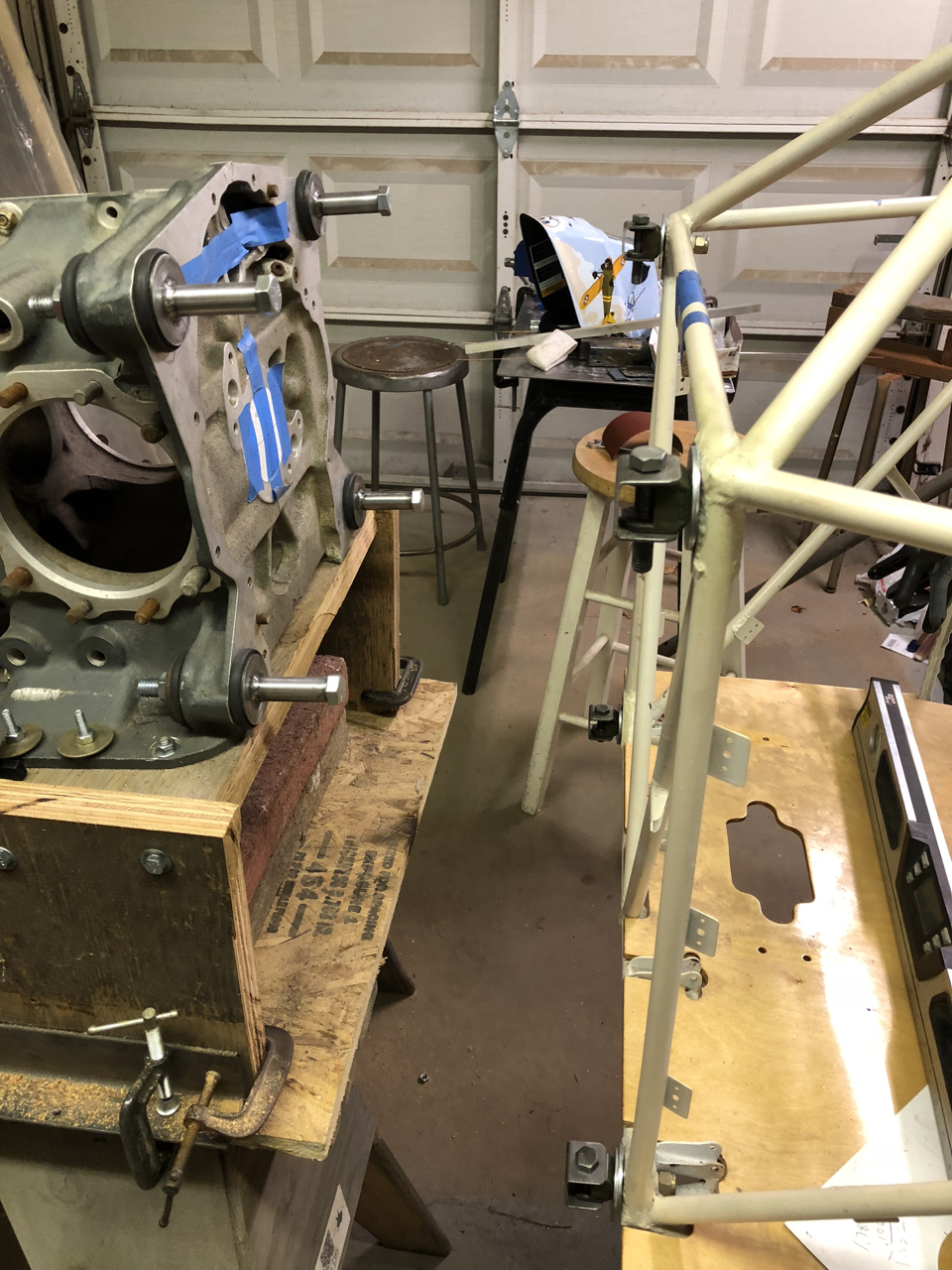
My first attempt to fit the factory mount …….
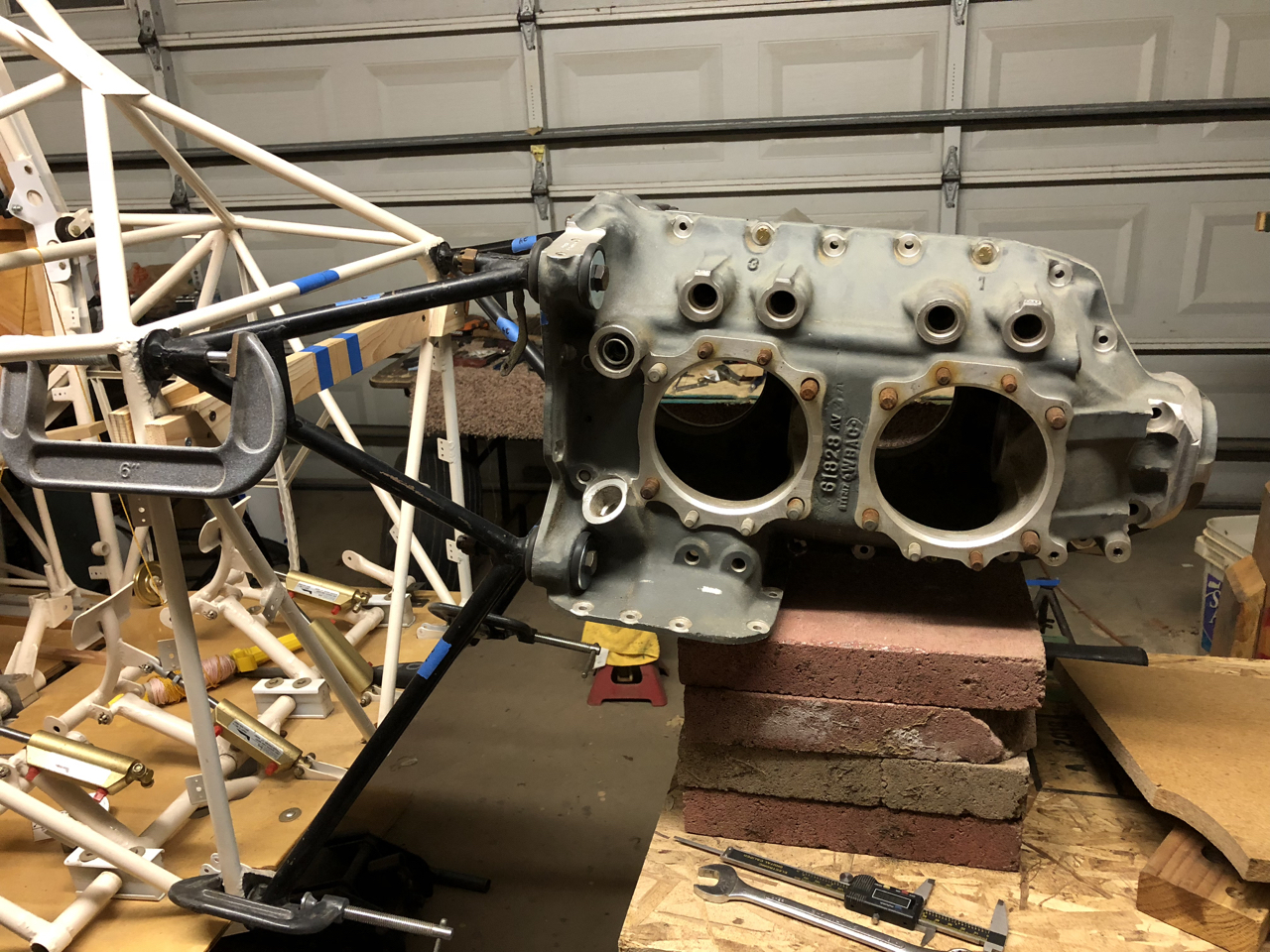
In the picture above, I attempted to fit the factory short mount and a bare case to the fuselage. The picture doesn’t show very well, but the bolts angles are off and the spacing is of by about 1/4” on the bottom of the mount. The clamps in the picture are holding the mount in place; I was not able to get the bolts to line up.
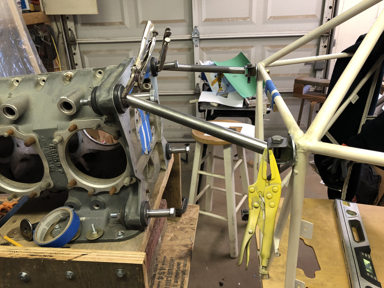
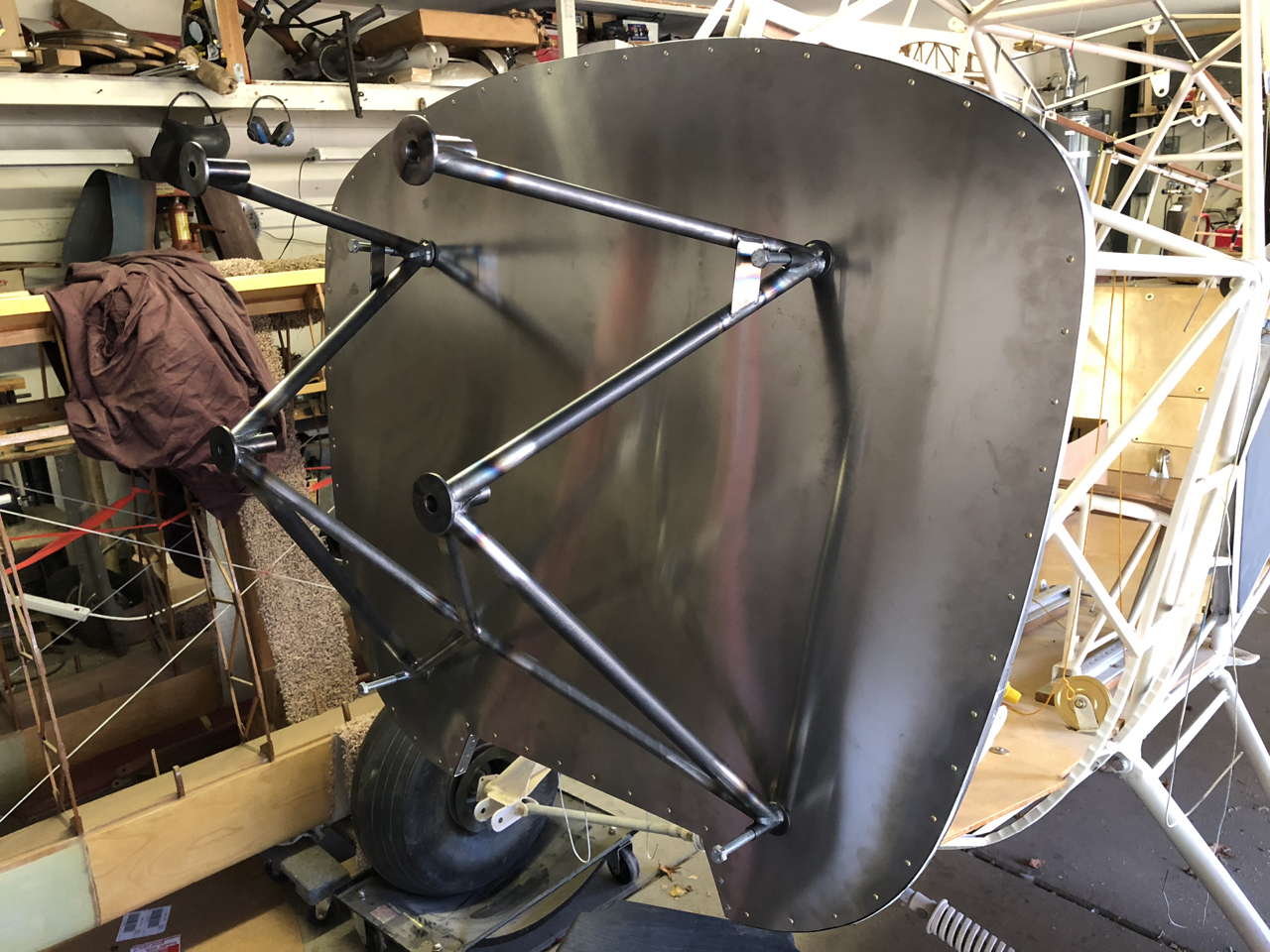
I attempted to modify a mount, it didn’t work. I decided to build a swing out mount using a bare case as the jig. I welded up my own mount ….. sort of successful but …… my gas welding caused too much distortion.
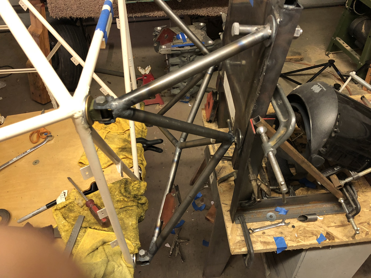
Above is a shot of that attempt. I first made a plate that represented the back of the case and set everything up to match the 4 degree tilt down of the engine as per Piper drawings. It looked ok but was too difficult to gas weld the area that bolts to the case (jig plate). Way too much heat was needed and too much distortion. After discussion with my building mentor, it was apparent that I needed to TIG weld a mount, jigged to my fuselage, to match the measurement issues of my fuselage rather than gas welding. I need to weld a mount with less heat distortion.
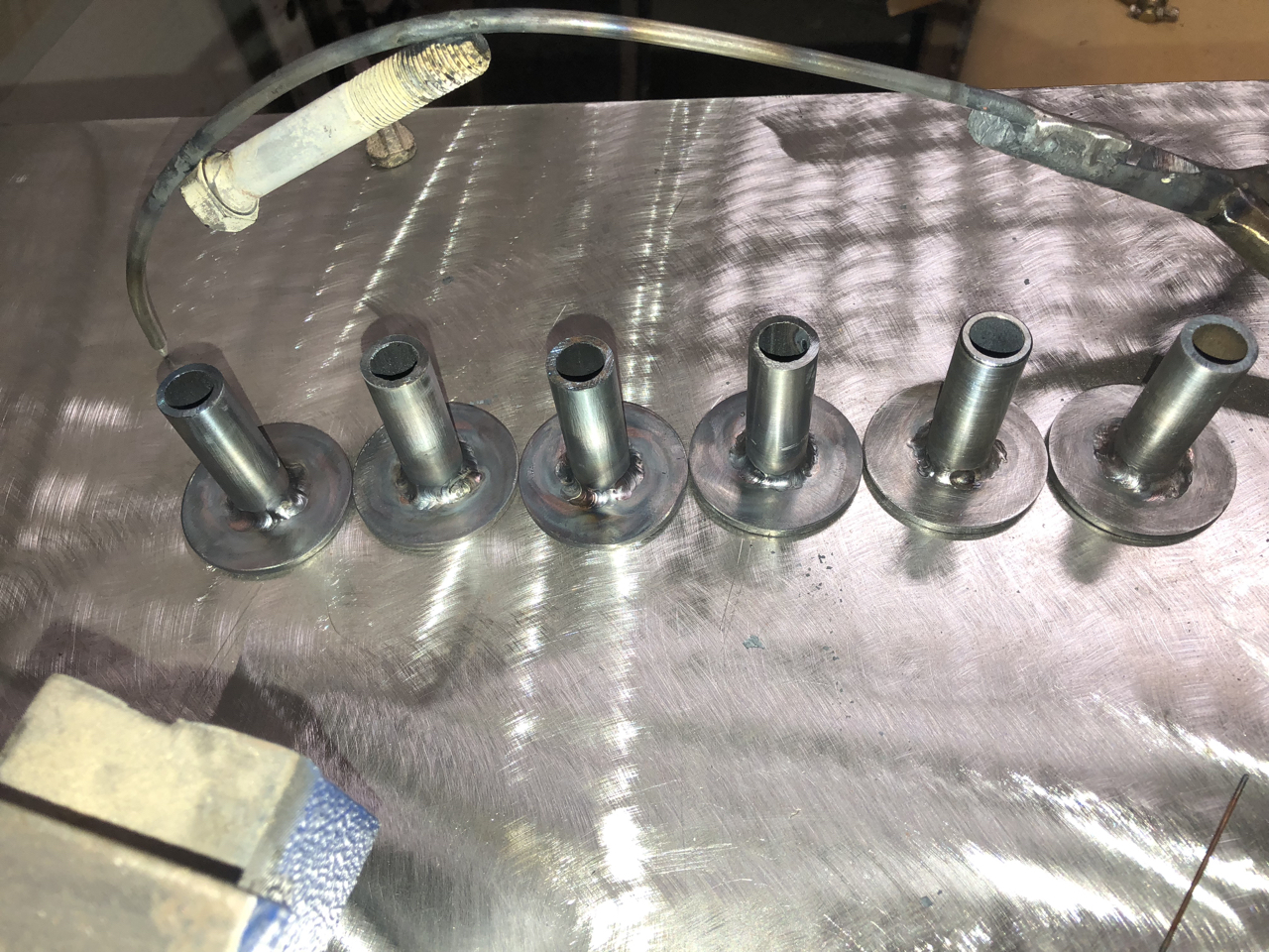
With a borrowed TIG welder, I attempted to learn to TIG weld. There was some success but lots of time spent. I did manage to weld up the lugs that bolt to a case.
Next, I jigged up an engine case in front of my fuselage; this time I would weld the mount using TIG. I spent a lot more time trying to perfect my welding ……. and I started the welding process.
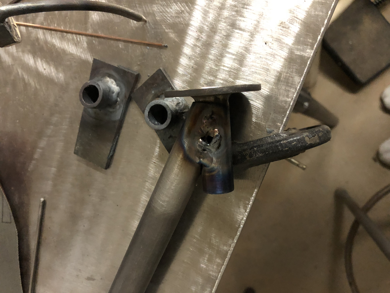
Lots of time was needed for fitting of the tubes. TIG welding requires a much more precise tube fit than gas welding so each tube took a long time to fit in place.
Burn baby, burn! I burned through my first tube.
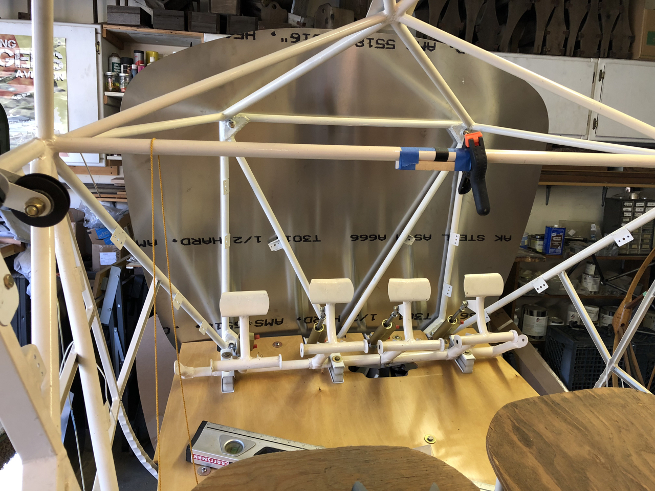
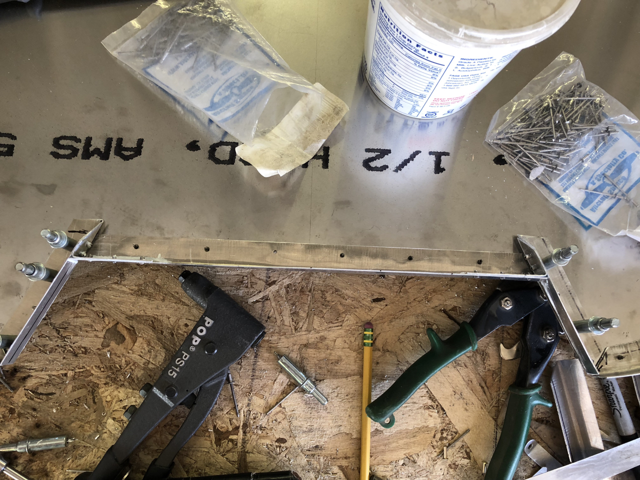
After all the work trying to get my TIG skills perfected, and attempting two different swung out mounts, I decided it was time to throw in the towel and have a mount made. I didn’t want to spend any more time trying to perfect my TIG welding so I decided to throw in the towel and have a mount built. I realized I would not trust my TIG skills on an engine mount, it is way too critical a part. I had already been in contact with Experimental Aircraft Metal Fabrication in Washington State and they were ready to build a mount to fit my fuselage. I first had to make a wood pattern of the bolt holes from my fuselage; a wood frame representing what the engine mount should be.
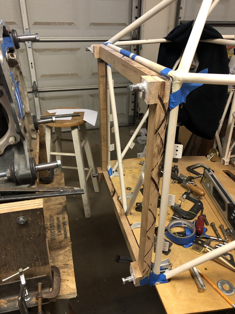
Then, from that wood engine mount pattern frame, I made a wood frame representing the front of my fuselage.
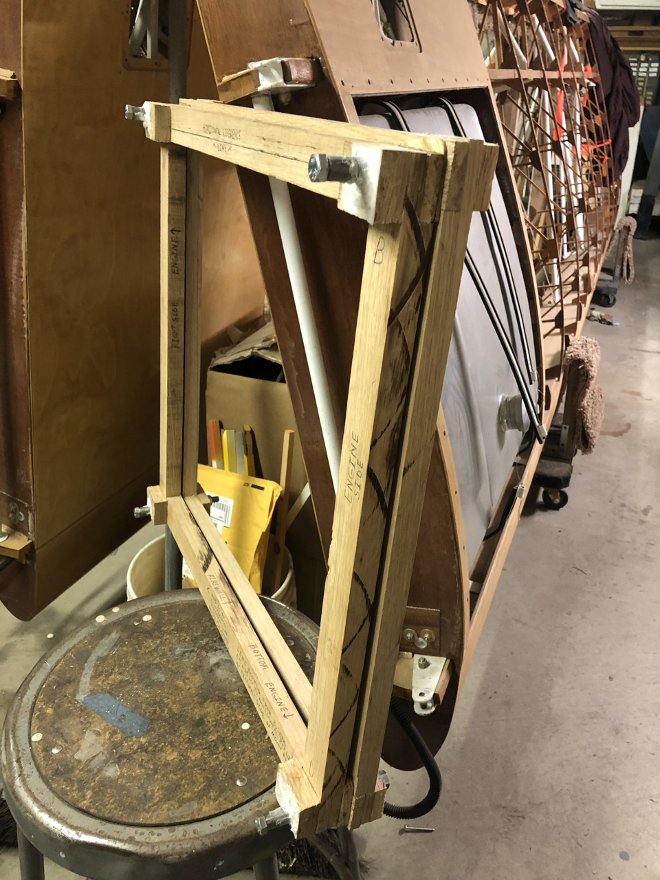
With the two frames done, I sent these off to Experimental Aircraft Metal Fabrication to have an engine mount built for me. While waiting, I started on my firewall.
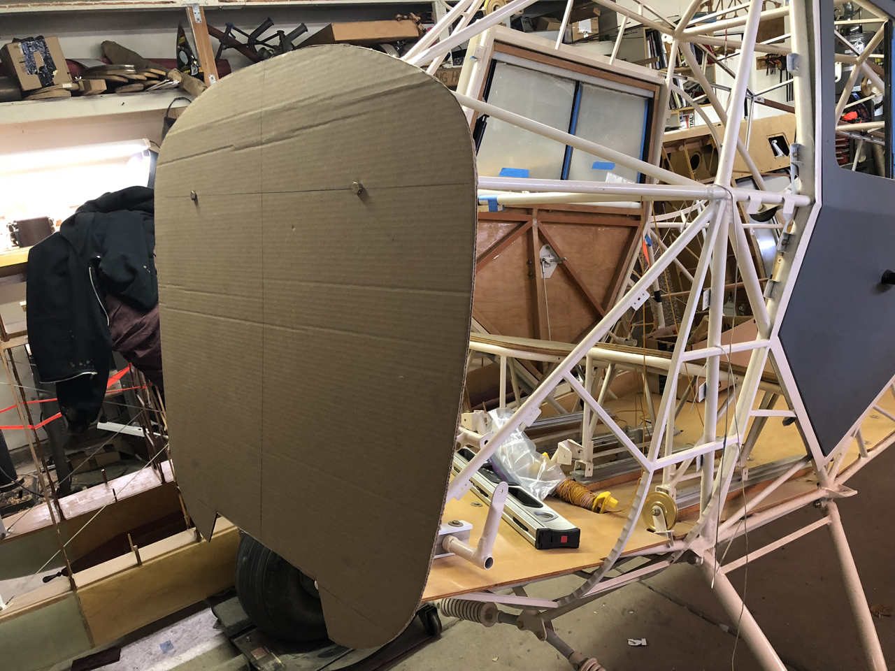
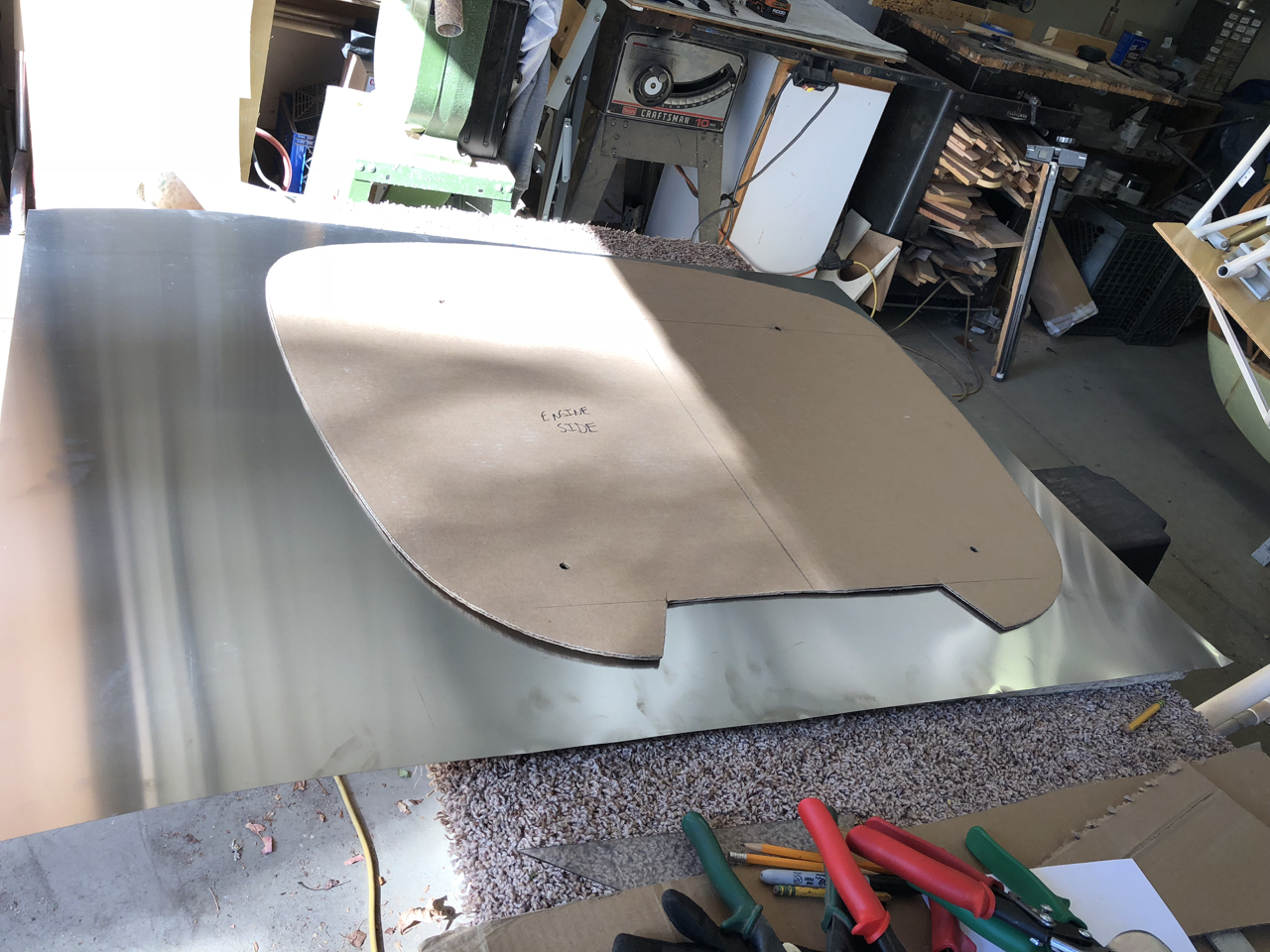
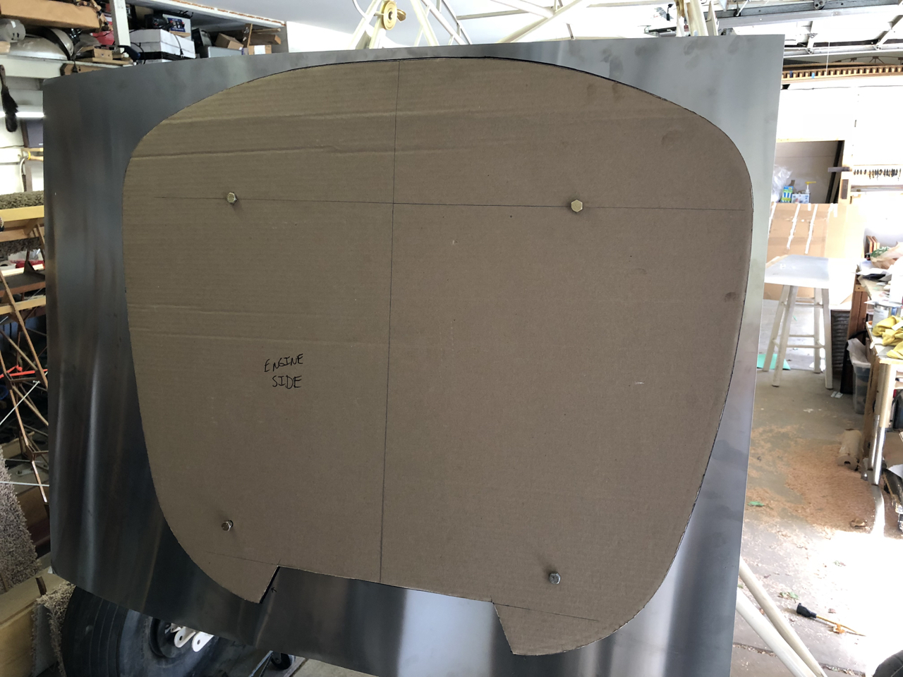
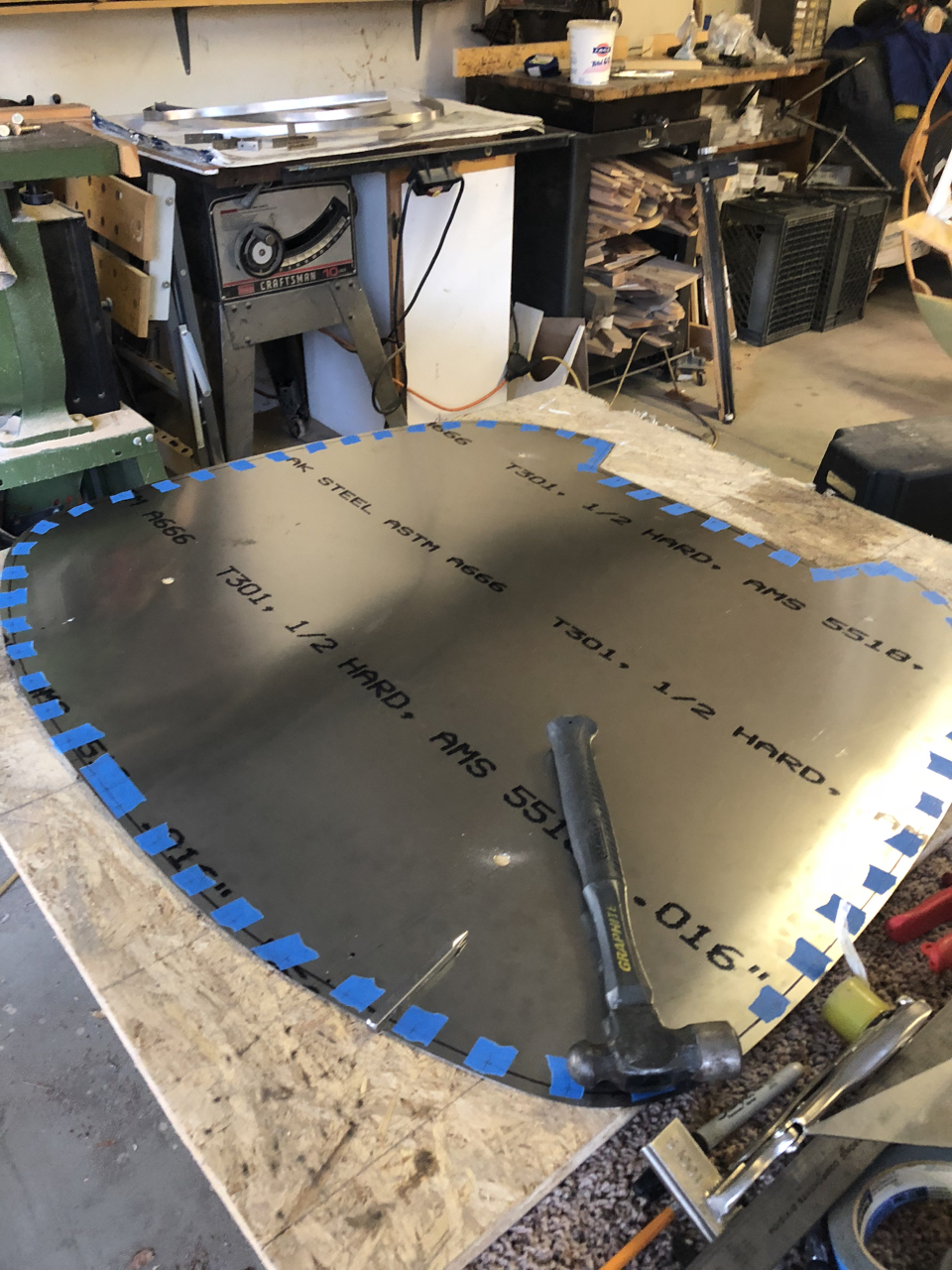
I decided to build a stainless steel firewall with an aluminum perimeter frame riveted in place. First, I made a cardboard pattern, then I cut and fit the stainless steel firewall.
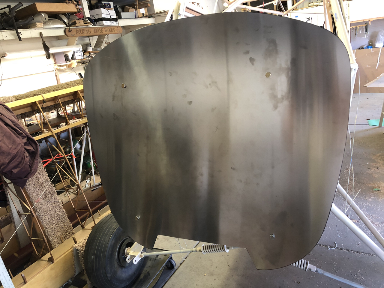
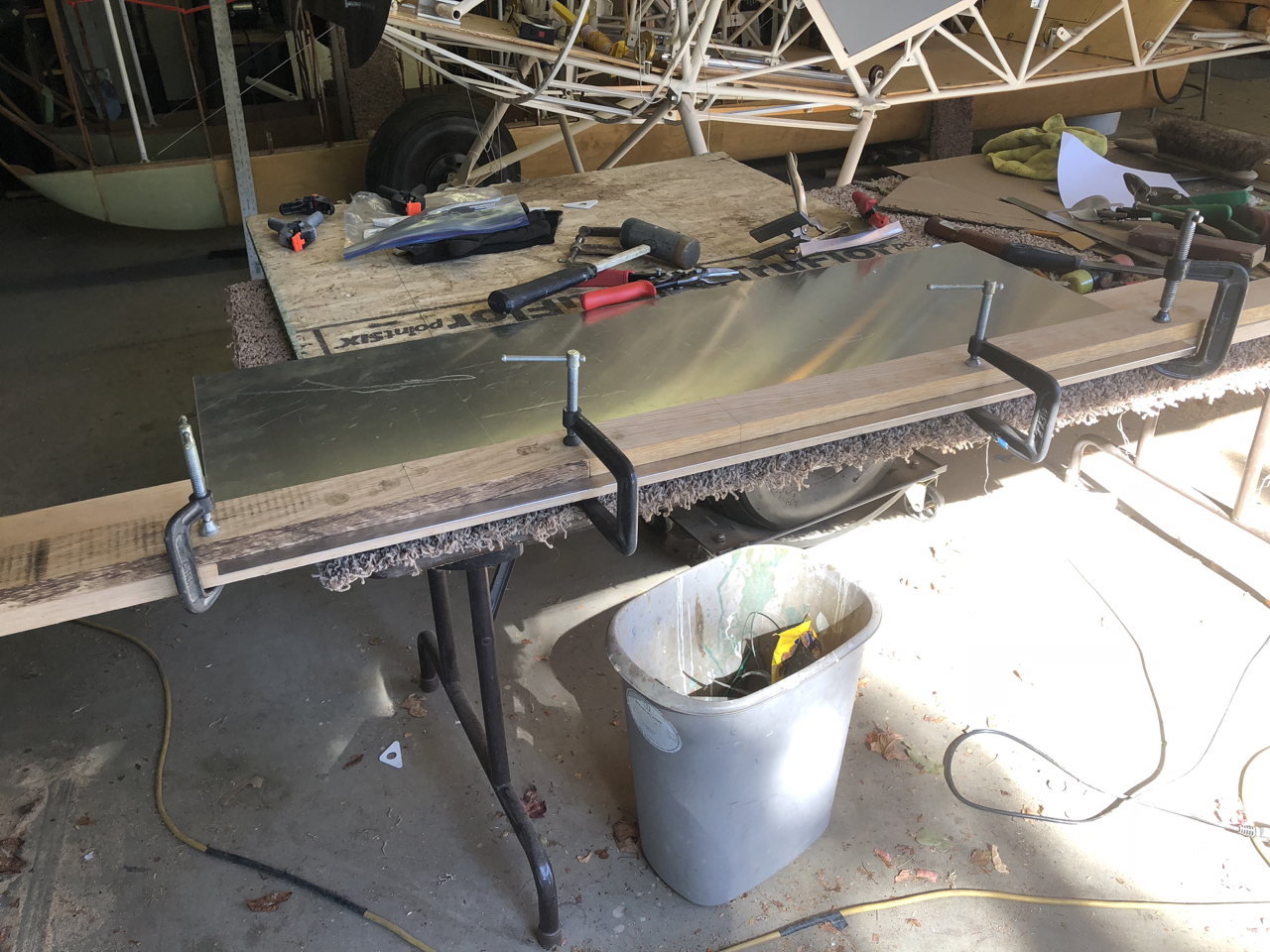
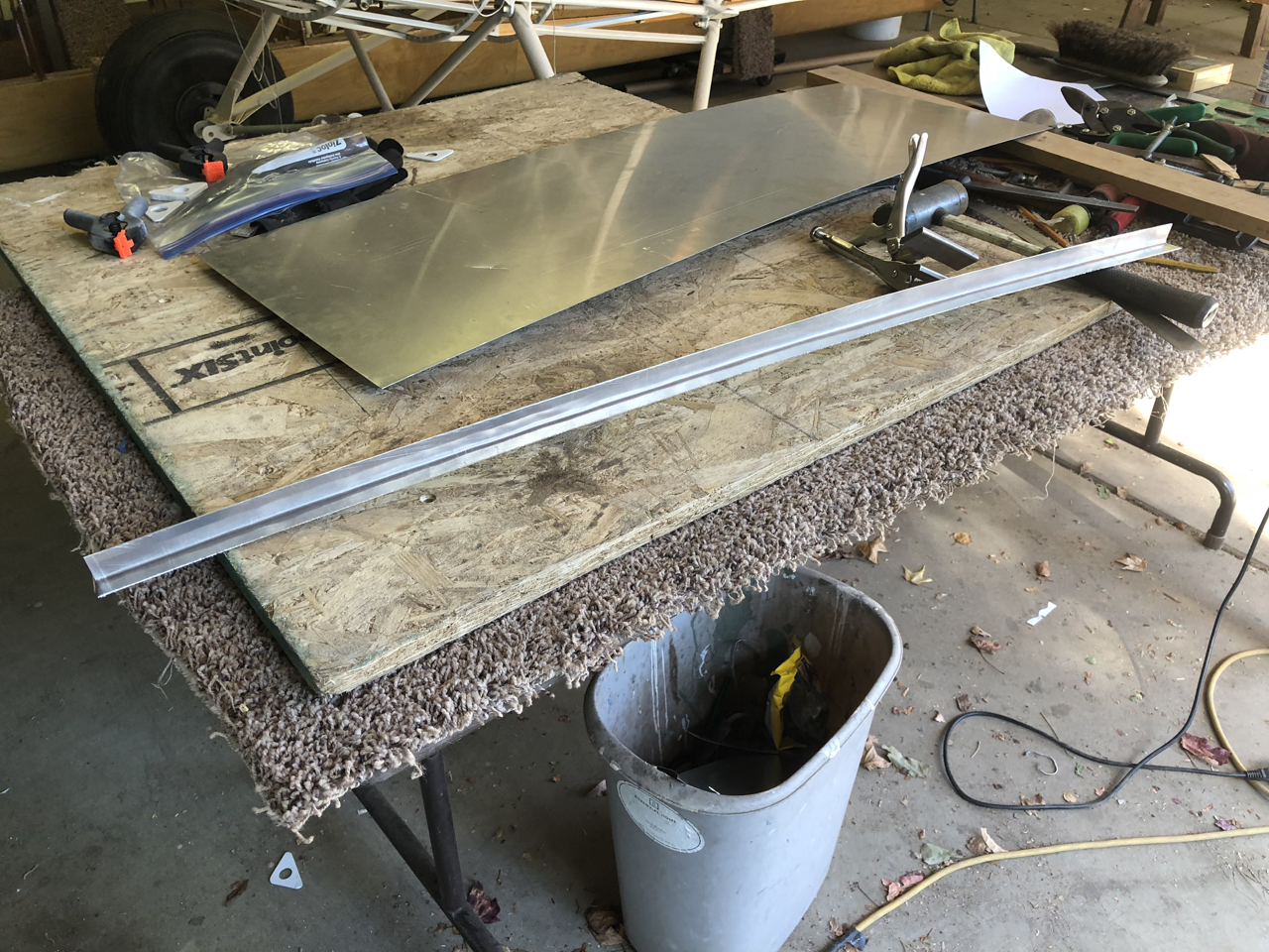
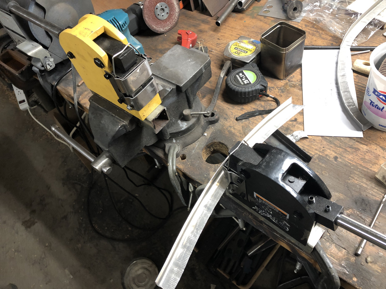
I did some planning on the locations of nut plates at the bottom for the boot cowl and fabricated the firewall flange. The process was pretty easy. I had never used a shrinker/stretcher before and it proved to be a fun process to learn. I only trashed one piece that I stretched too much and it fatigued and cracked. The rest was very easy. I first bent the aluminum strips into aluminum angle that would then be bent to fit the curve of the firewall using the shrinker and stretchers.
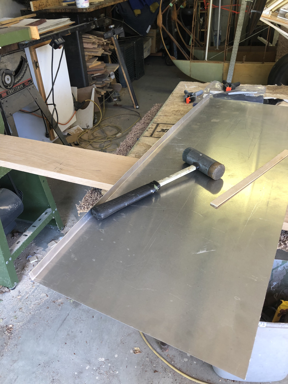
I bent the aluminum strips into angles using a couple pieces of wood and a rubber hammer.
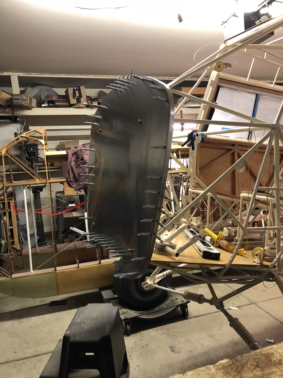
Next, I planned the hole locations to take into account the mounting channels from firewall to nose bowl. Hole locations were marked on the firewall with tape and center punched prior to drilling.
After the firewall was drilled, each flange piece was bent, drilled, and Clecoed in place as I went around. I bent and fitted the four main flange pieces using my Harbor Freight Shrinker/ Stretcher.


I fitted the bottom section next, setting a few nut plates in the process. Other nut plates will fit between the rivets so they can be added later as I build the boot cowl pattern.
Some test fitting ……
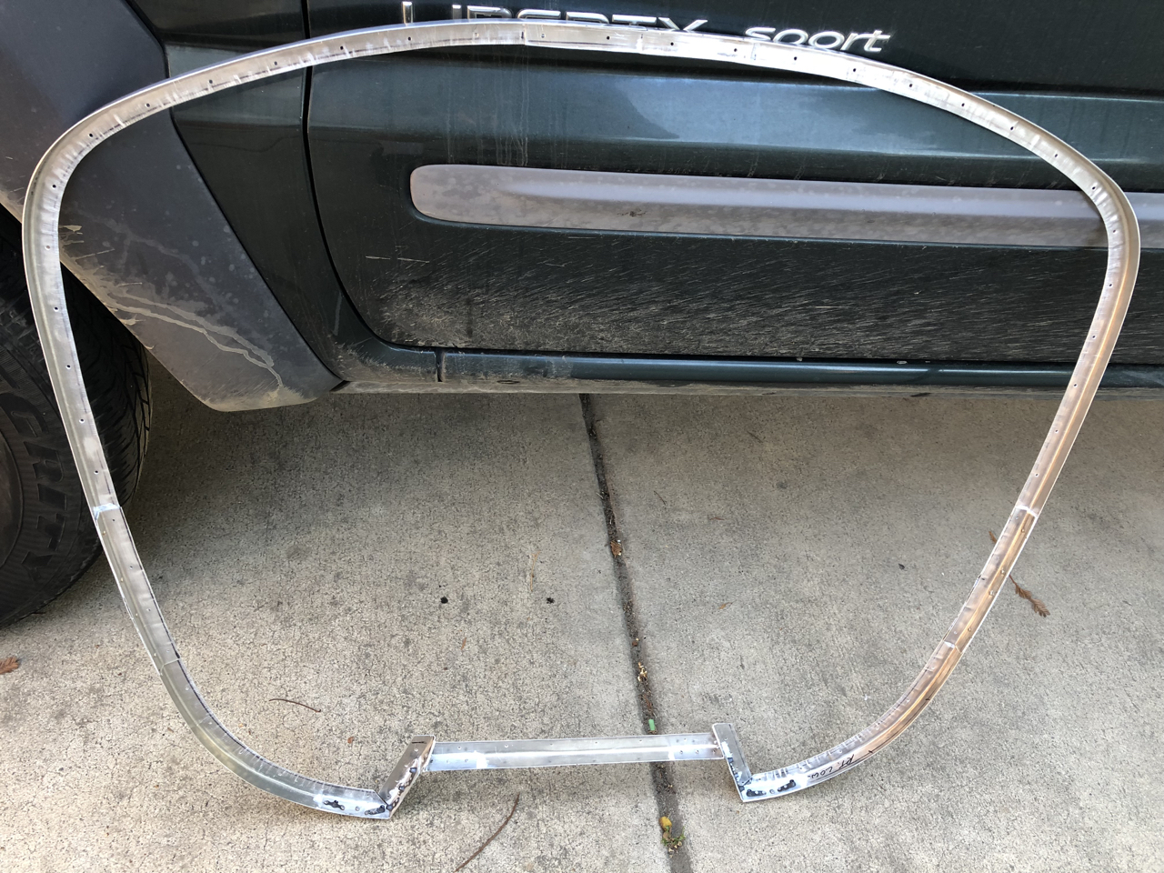
Here’s the finished flange prior to riveting to firewall.
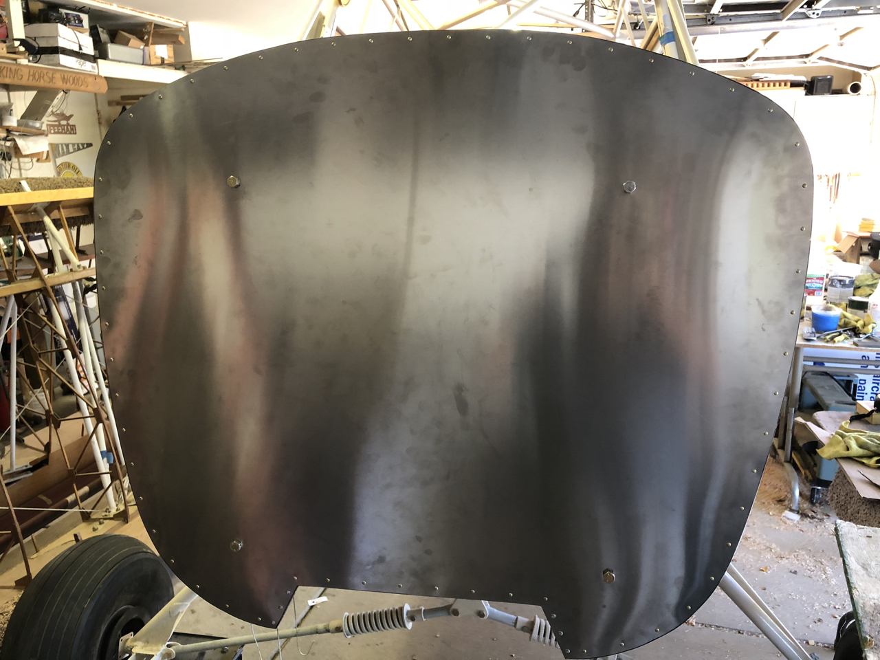
Everything riveted in place and on the firewall …...
The day after I finished the firewall, October 31st, the engine mount arrived from Washington. I now had a custom built engine mount that fit my fuselage and was ready to move forward on the boot cowl.
After the firewall was done, I started on the patterns for the boot cowl. You will first need to make a pattern of the instrument panel and place it in the fuselage. The instrument panel becomes the back former of the boot cowl. The patterns are made from poster board or similar cardboard; I use free cardboard from Costco. Just go to Costco toward the middle of the day and pick up the type of cardboard you need from the pallets of food around the store. They never question me as I leave with 4 or 5 sheets; they are happy to get rid of it rather than paying to have it hauled away.
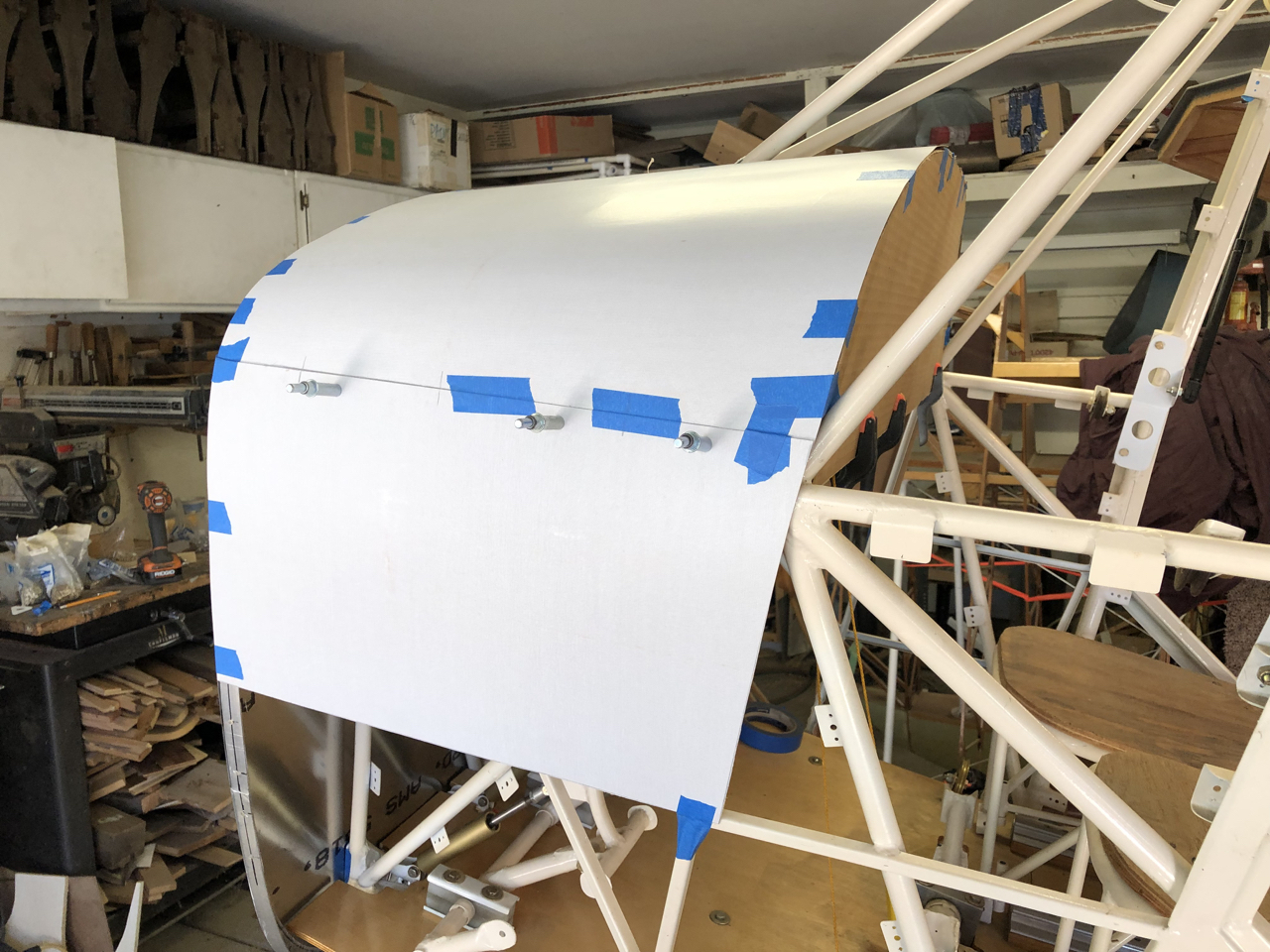
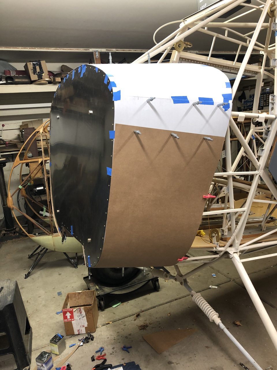
Some shots of the pattern work follows. I rough cut the patterns, taped in place, and Clecoed the card stock together to form up the boot cowl. I’m making a three piece cowl and will be able to show the patterns after they are all fitted and I figure where the break will be based on nut plate spacing and existing fuselage channels.
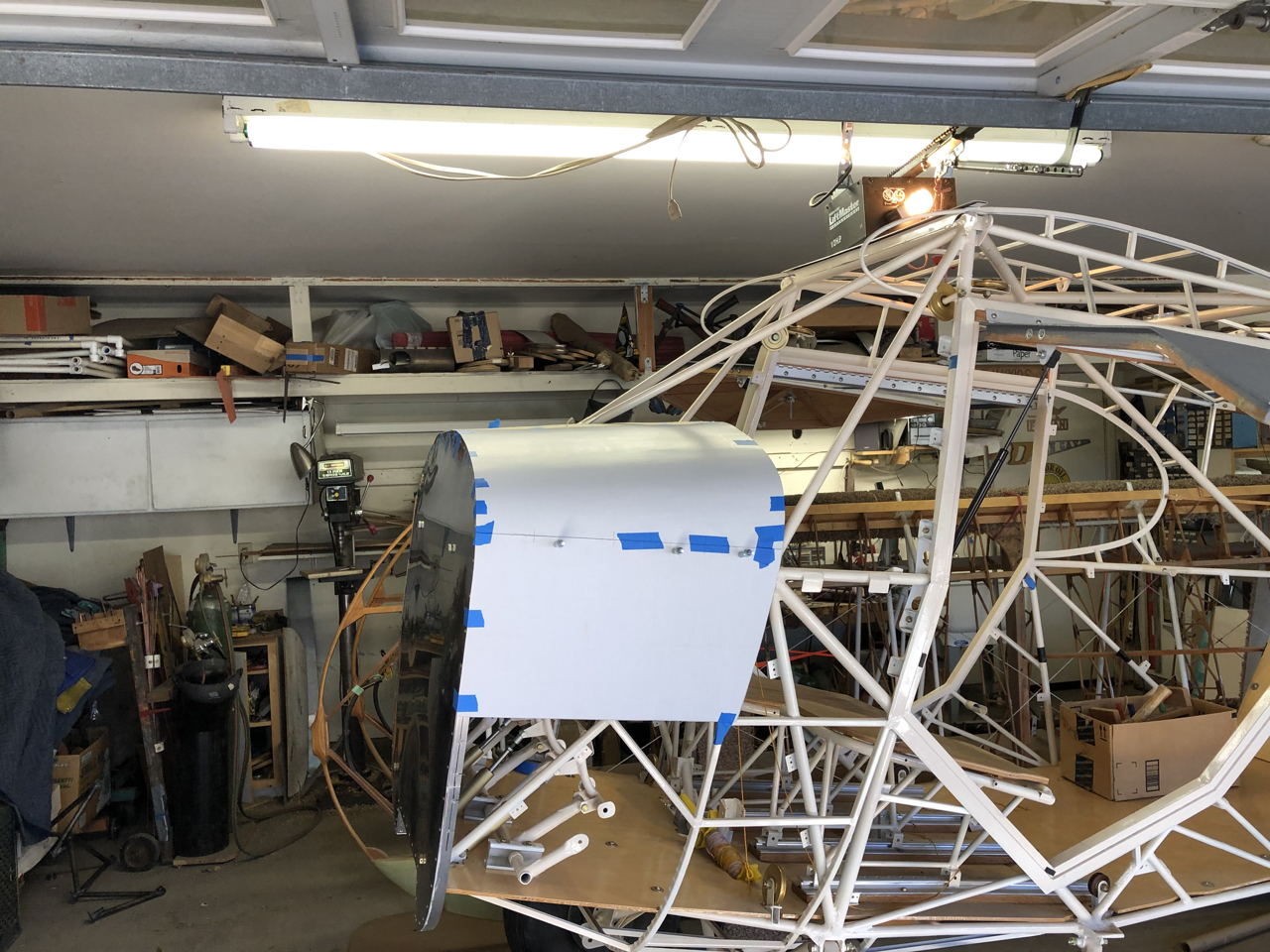
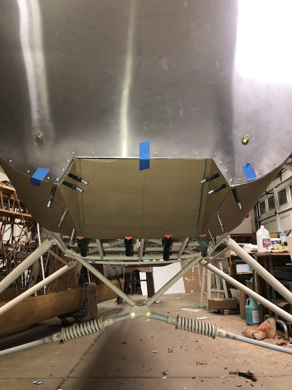
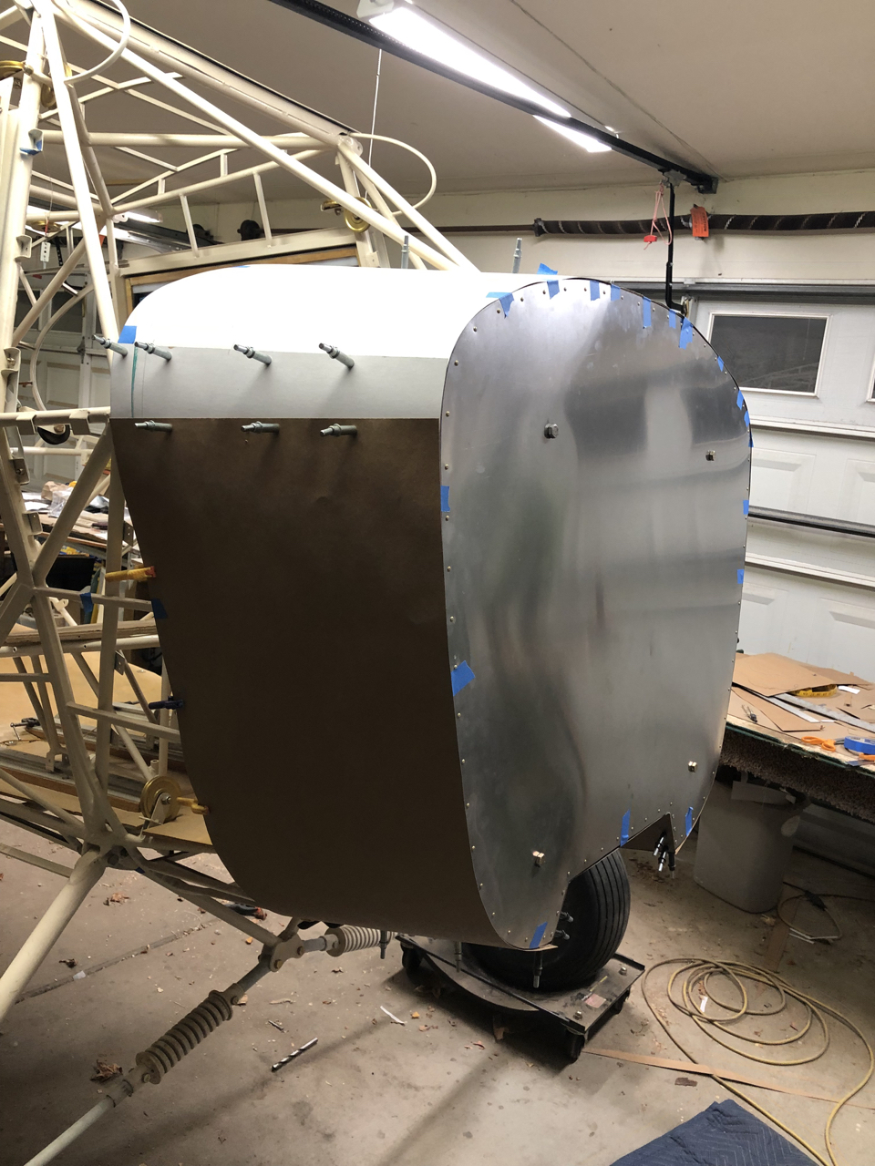
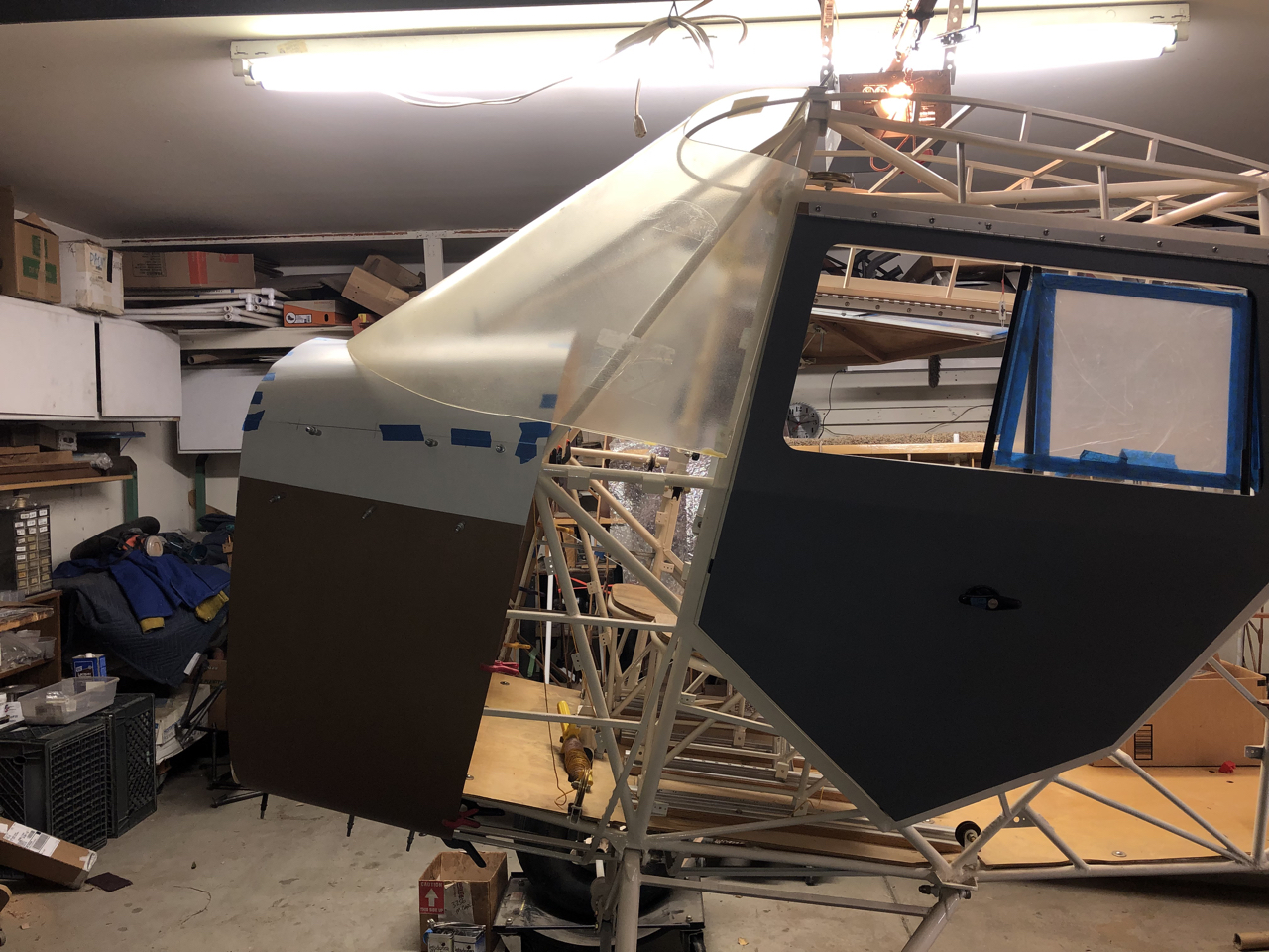
I finished the cardboard version of the boot cowl and will be getting the aluminum soon and make the real thing. I also set in place, for the first time, the windshield to check for fit. First placement looks ok and have been figuring out how that will all come together.
Next step, building the boot cowl in aluminum.
Return to Past Posts and Pictures by Date