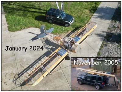

I finally finished my wood aileron about a week ago. I decided to wait to post till I had some time on my hands after another foot surgery yesterday. I have been posting on the Super Cub site also but wanted everything here. I just uploaded all my pictures for the aileron build here so you can see how it all went together. All in all, the build resulted in a great finished aileron. Like everything on my project, I learned a lot and had some set backs along the way. I have already put these into play on the wood flap; just about finished and a lot less time and heart ache. Below is a picture of the finished aileron followed by step-by-step construction.
Let me show the entire process here from start to finish. These were built from plans I received from another builder. I plan on re-drawing everything with cad during my recovery these next few weeks and posting them for other builders use.
I will be building these exactly the same as stock Super Cub ailerons and flaps; just out of wood. The hinges are the same; lengths same as stock; and stock cord length. The only deviation is the hinge location. The first hinge is off set about 1/4″ to accommodate the location of my hinges. I placed the hinges according to the 2+2 drawings and they intend use of stock Piper ailerons. I added the wood wing tip; not on the plans and that resulted in the 1/4″ difference. The difference is from the inside of the tip rib to the first hinge, nothing different from there. So, here we go.
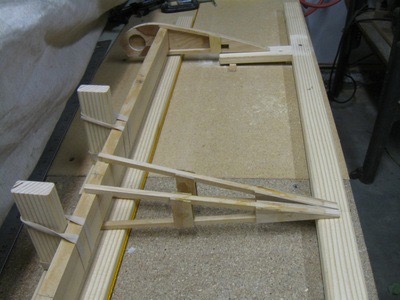
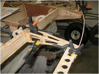
 I got the jig ready to start the
fitting and assembly process. I will need to do final fitting and adjustments
before gluing but I am ready to begin. Lets take a look where I am at.
I got the jig ready to start the
fitting and assembly process. I will need to do final fitting and adjustments
before gluing but I am ready to begin. Lets take a look where I am at.
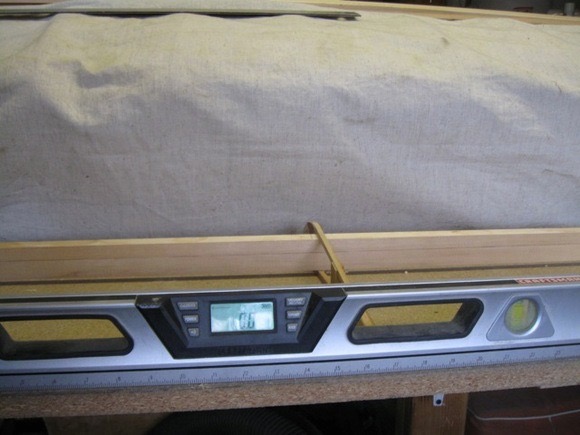
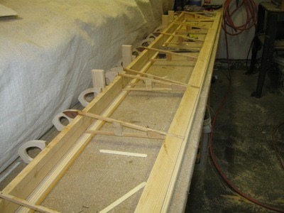
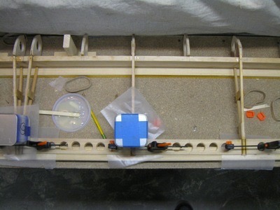
First; I extended my table with partial board, and set everything to level. I got the length to within 0.1 degrees and I think that is going to be good.
I used the table to adjust and plane the spar for fit. I removed a bit of wood from the edge and made sure the spar was flat. The ribs need to float on the spar so they can be rotated to establish the wash out. If the ribs are tight than they can’t rotate forward without twisting the spar.
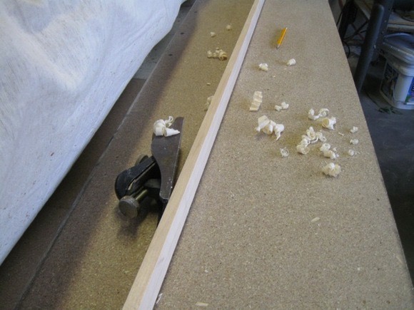 Table ready and flat.
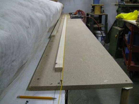 Next, I set a string line and secured a piece of wood to support the front edge of the ribs as I fit up the ribs.
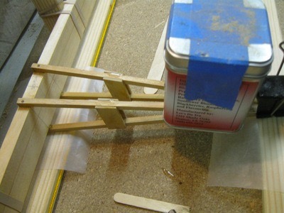
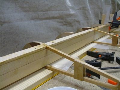
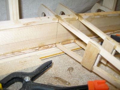
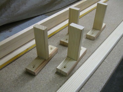 I made some “T” blocks to hold the spar true to the angle established by the ribs, The blocks will be screwed to the table and the spar clamped in place to keep the spar from twisting when setting the ribs for wash out.
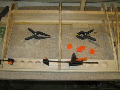
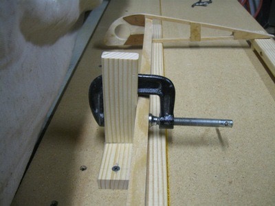 The second strip above will be shimmed to provide the washout. I placed a 3/8″ block under the strip at the end and a 3/16″ block at mid point to set a point for each rib tail to set on for the wash out.
 This picture shows the blocks, spar, and shim all acting together to establish the 3/8″ wash out.
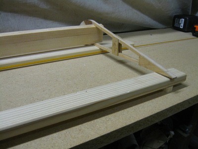
 Here’s a shot of the other end, no shim. I have a 3/16″ shim in the middle of the strip. I will put additional shims to keep the strip level from end to the 3/8″ block.
 So now you get the idea of how I will be assembling the aileron. Next, some pictures of other parts of the ailerons.
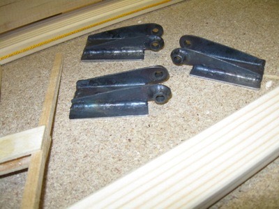 These are some of the hinges I made. These are as per the drawings; looks the same as stock Piper. I still need to paint these metal parts.
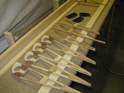
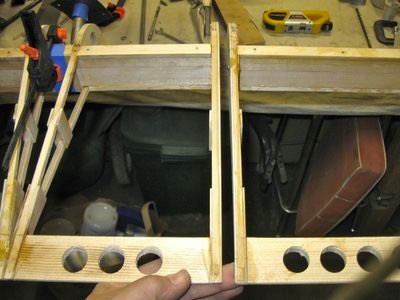
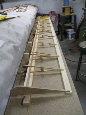 The next step is to fit all the ribs before gluing in place.
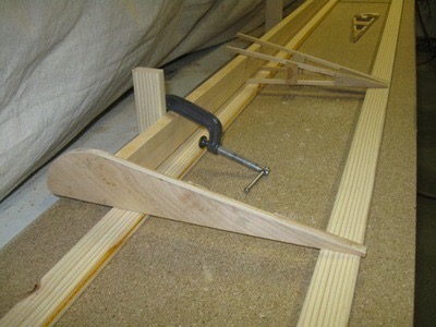
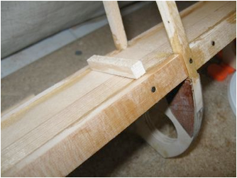
 This picture above shows the tip rib set up with a 3/8″ block for washout as per the Super Cub aileron drawing.
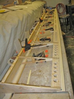
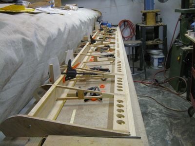
 Next, gluing up the ribs. I secured the spar at the proper angle and the rear strip supporting the trailing edge creates the proper washout. By doing this there will be no twisting on the spar and therefore no binding induced on the hinge pins.
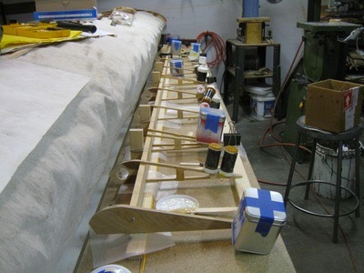
 The containers on the ribs hold lead shot for weight to help keep everything in proper alignment. I also used small rib nails to hold the wood in alignment as the T-88 epoxy dries.
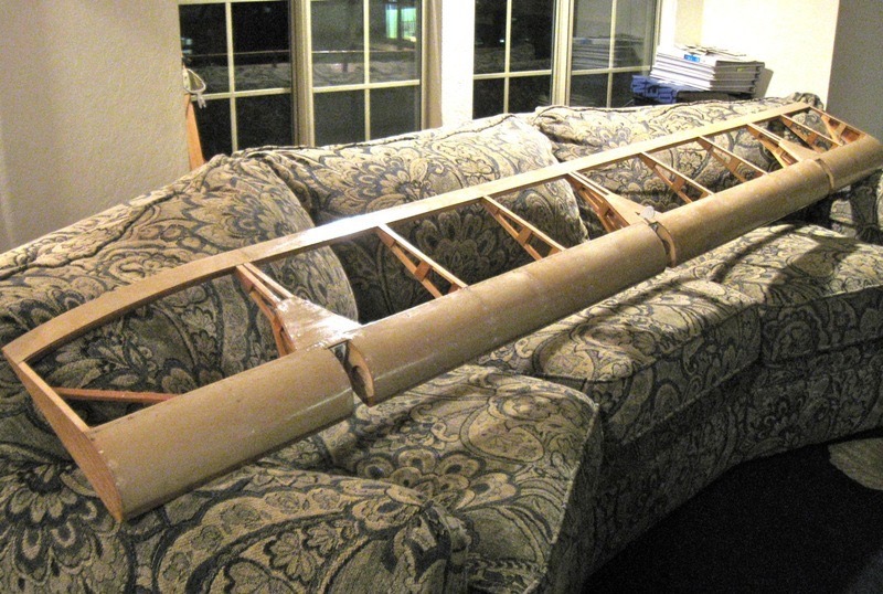
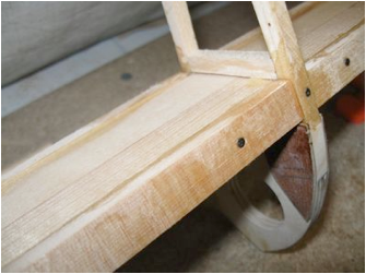
I should be able to remove it from the jig tomorrow. This last picture above shows the attachment of the ribs at the hinge point. Nose ribs will be attached latter along with reinforcement ply and the hinges. This next shot was from one of those rare Saturday’s that I was able to work un-interrupted, so lots of progress.
 First, I made all the nose ribs for both the ailerons and flaps. I used a router with a laminate trimming bit to duplicate the parts. I hadn’t made them back when I assembled the ribs with the wing ribs during the summer assembly weeks.
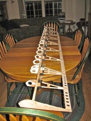
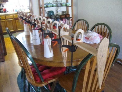 Next, after gluing them on in the shop, I brought the aileron inside to cure the T-88 faster at room temp. Yes, that is our dining room table and yes my wife was home at the time.
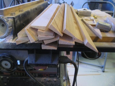 Next, I made all the trailing edge stock needed for all the control surfaces. I used the table saw for this step; pretty easy.
 The next step was to fit pieces of trailing edge stock between ribs. Again, an easy task.
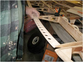
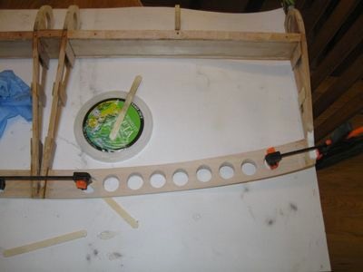
 The last thing I did that night was to make a template to lay out the locations for lightening holes in the trailing edge stock. The top material will be 1-1/16″ ply over the edge material so they will be very strong when finished.
 I drilled the first two pieces and did a test fit with clamps. After finishing up the drilling I glued all the straight trailing edge material in place.
 I was able to get out into the shop a couple of hours after work Monday and get some more steps complete. First, I unclamped the trailing edge and did some preliminary sanding. I will need to do a little bit more before sheeting with 1/16″ ply.
 Next, I cut some strips of spruce for the spar cap. The spar is capped with 1/4″ x 1/2″ strips to bring the spar up to the level of the ribs for gluing of the leading edge ply. Here are a few shots.
 Spar caps nailed and glued in place.
You can see I used nails to hold everything in place here to speed things up. Next step is capping the bottom of the spar; same size spruce strips. If you haven’t built a wood wing then these posts may seem like there are lots of steps and lots of pieces ….. and you are right! The total time involved so far is not much; maybe 10-15 hours. That may seem like a lot but is normal for wood wings. Each step has to dry over night, so you have to take your time. To make a comparison to a metal aileron you would have to scratch build everything, starting with sheet metal and forming all the ribs using a wood block, bending your own spar, and rolling your own leading edge material. Time would likely be about the same compared with wood.
 This picture shows both the top and bottom of the spar with caps in place.
 Next, the remaining upright spruce for the ribs needed to be cut and glued in place. I left this out so the rib could be rotated slightly to establish the 3/8″ washout. Gussets will be added to tie the upright to the upper and lower cap strip. Although this seems like tedious and insignificant, this piece will help transfer the aerodynamic loads from the surface to the spar. Before adding the gussets, I needed to cut and glue a 1/16″ reinforcement plate at the hinge locations. The ply is glued with the grain vertical over the horizontal spar and over the spar cap. This laminate will make for a very solid point for the hinges. The hinges will be bolted in place with AN3 bolts secured to a rear .040 4130 plate with nuts secured in place. There is lots of step-by-step that is not in any drawings but comes by experience from building wood wings.
 Spruce upright added. Gussets will be needed to tie this into the cap strip.
 Plywood added to the inside face of the spar for the attachment of the hinge latter.
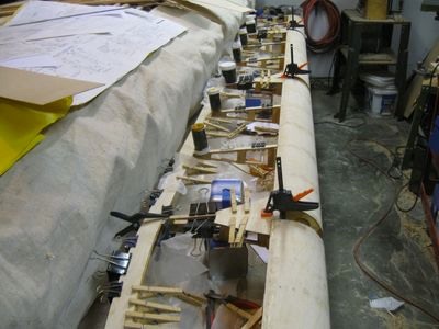
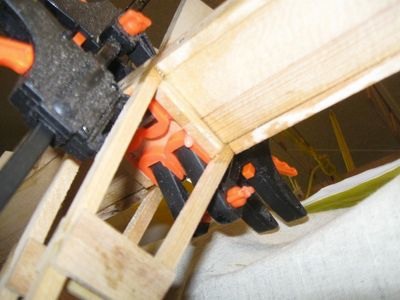 Four clamps and time to dry over night.
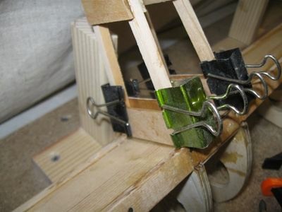 After final sanding on the gussets I glued them in place. Binder clips from Staples make great clamps.
 More binder clips.
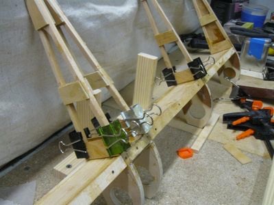
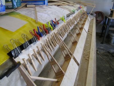
 Everything inside to dry over night in the warmer house ……
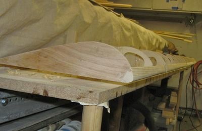
Since I made my wing with the wood tip bow I needed to follow the curve into the aileron. The plans call for a stock trailing edge with 3/8″ .035 tube bent for the curve. I decided to go with a wood trailing edge to be covered with 1/16″ ply. The curved end was evading me until last night. I came up with what now seems to be the only logical approach: duplicate the wood trailing edge profile in a curved piece of wood.
 First, establish a curve and make a paper pattern.
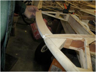 Then I cut a curved piece of spruce to test fit from the paper pattern and drilled the holes to match the rest of the trailing edge. This was test fit, sanded and glued into place.
Checking fit before gluing in the curved piece. This piece has the same tapered thickness from inside edge to outside trailing edge as the rest of the trailing edge pieces.
 Back inside the warm house for gluing and drying overnight.
 Clamped and drying.
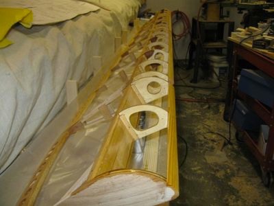
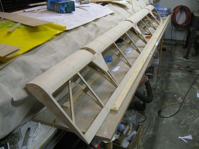
I decided to build up the matching wood flap for the wing. I needed the flap and aileron hanging together to determine the proper location of the hinges. My hinges are stock but will bolt to the flap and aileron spars; making them removable if necessary down the line. The retaining nuts will not be directly accessible but a 1″ hole could be drilled for access if necessary requiring only a small patch; more on that latter.
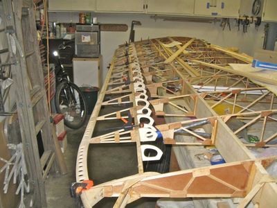 This is the first hanging of both control surfaces; the fit turned out great. The only adjustment I needed to do was a /16″ shim under the aileron hinge closest to the flap. That was needed to compensate for an extra washer I had to add under the aileron hanger to align the three hinges. The spar already has 1/16″ ply glued to the front and back for reinforcement so I just needed to glue on another 1/16″ thick reinforcement piece for the alignment issues. I glued those on last night along with the single 1/16″ reinforcement on the front and rear spar of the flap hinge point.
Testing fit between flap and aileron. Looks good!
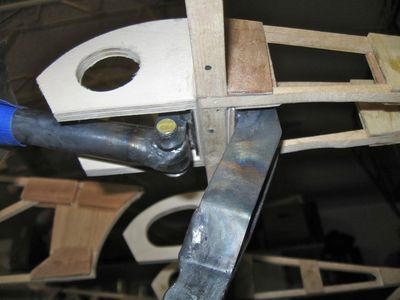
 The next step required building the aileron horn. I had been working away for the about three weeks on steps requiring some “learning curve” and some design work. I fabricated the aileron control horn first as per the plans than modified to remove some sharp corners and excess metal. The horn and hinge are one piece on the plans and I wanted them separate and removable from the ailerons easily. The horn is on the back of the spar and the nine on the front with two AN3 bolts going through them and the spar. The set up worked out real well after a bit of work. The design is very similar to that of a Pacer so nothing very different from what has been done in the past.
 Test fitting the aileron horn.
 Next, I added a solid piece to the leading edge and shaped it to fit the profile of the ribs. This will allow attaching the 1/16″ ply in two pieces. Everything needed to be sealed inside with epoxy before attaching the leading edges.
Leading edge inplace.
 Next I attached the plywood with aircraft nails to hold the skins in place. This went pretty smooth and I thought I was very happy but………
The nails proved to be a very big problem to remove. I made a small puller that I thought would work but it proved to be very time consuming to get out each nail. Hind sight being what it is I should have left the nails in but I want a very smooth surface so the nails had to go. Next entry will show the trials and tribulations. After the fact I found a method to set the nails for easier removal but not until they were all in place. I have mother idea for the flaps and other aileron that should be easier. We’ll see.
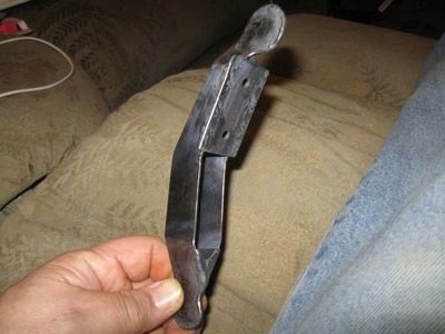
So much for a good idea. The nails were a good idea for holding down the plywood but removing them proved to be a tedious task at best. I had in mind a tool to use to remove the nails. I fashioned a little puller from a wood-carving tool to be used in conjunction with a small side cutter. Although it worked, it did not work well. Most of the heads were popping off requiring digging out the nails. The combo worked well on flat areas but not at all on the curved surface. Here’s the tool:
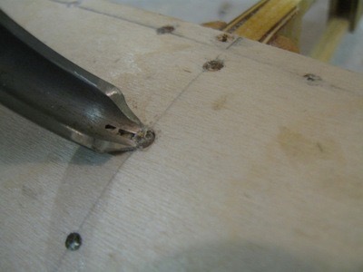 The problem was gripping the nail low
enough below the head to not cut off the head. So, I did some head scratching
and decided to use a “hollow drill bit” of sorts to cut around the head of the
nail.
The problem was gripping the nail low
enough below the head to not cut off the head. So, I did some head scratching
and decided to use a “hollow drill bit” of sorts to cut around the head of the
nail.
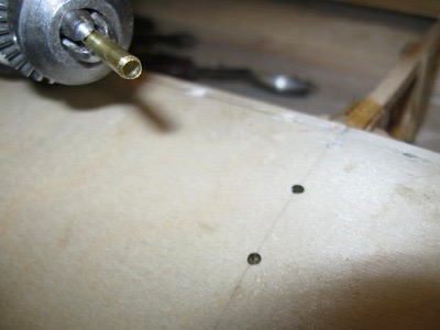 Here’s the “drill” made from a piece of hobby shop brass tubing that just fit over the head. It had to be sharpened often but my Dremmel with a small grinder and the brass spinning in the drill made that very easy.
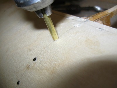 This worked pretty well. It exposed
enough of the nail head that I was able to get below the head and tease the
nail up above the ply enough to use a very small diagonal cutter to do the
final removal.
This worked pretty well. It exposed
enough of the nail head that I was able to get below the head and tease the
nail up above the ply enough to use a very small diagonal cutter to do the
final removal.
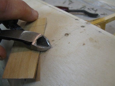 My little puller made from the carving tool now worked to get the head up just enough to use the small diagonal cutters to pull the nail out completely.
 Now I have to fill each hole. That
won’t be difficult. I will mix up epoxy and mix in micro balloons to make a
very strong and light weight filler. Using a small squeegee I’ll fill the holes
and lightly sand smooth. So how to avoid this? I found out after the fact in “The
Sportplane Builder” by Tony Bingelis (pg. 70) shows a way to use small nail
strips with wax paper. Nails are pre set into 1/16″ strips of wood and nailed into the skins
with was paper to hold down as glue dries (looks like a carpet nails strip).
The wood strip is latter removed and any nails left can be removed using a
diagonal cutter. On the Biplane builders site I came across this a thread about
this and the builder still had some difficulty removing the wood and
nails.
Now I have to fill each hole. That
won’t be difficult. I will mix up epoxy and mix in micro balloons to make a
very strong and light weight filler. Using a small squeegee I’ll fill the holes
and lightly sand smooth. So how to avoid this? I found out after the fact in “The
Sportplane Builder” by Tony Bingelis (pg. 70) shows a way to use small nail
strips with wax paper. Nails are pre set into 1/16″ strips of wood and nailed into the skins
with was paper to hold down as glue dries (looks like a carpet nails strip).
The wood strip is latter removed and any nails left can be removed using a
diagonal cutter. On the Biplane builders site I came across this a thread about
this and the builder still had some difficulty removing the wood and
nails.
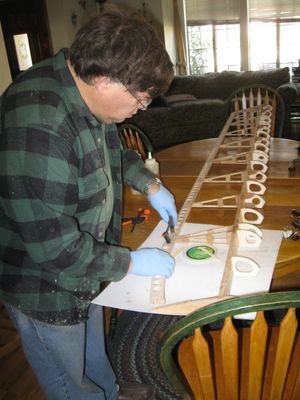
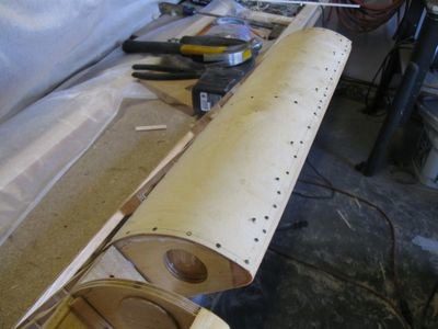
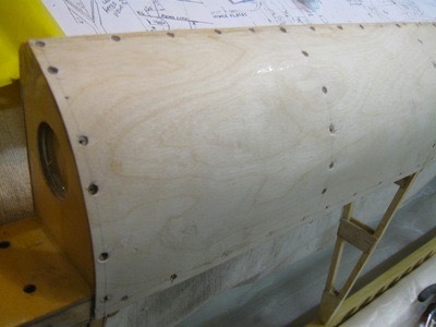
 Next, final pieces of 1/16″ ply. This brought everything up to level on all surfaces. There are no bumps, rivets, or screws sticking above any surfaces. This should make for a very smooth surface for applying the fabric. I also added the ply around the hinges. Just about done. Time to install hinges and epoxy everything.
 Adding the final 1/16" ply.
 Control horn painted and in place.
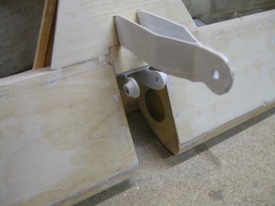
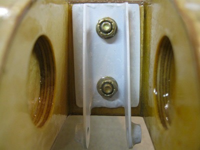 Here is a nice shot of the hinge bolted in place. (I latter added a third bolt in the middle of the hinge)
 And here we have the aileron before and after final varnishing.
 I wound up having to adjust the ply
under the first hinge as it interfered with the clevis pin but that was not a
big deal. I have the flap about done and will post pictures with the nail
strips I used and a very cool nail pulling tool that cut the nail removal from
10 hours to 1 hour. Total weight of the finished aileron is 8 lbs.
I talked to builders with metal ailerons and the weight range was from 7 to 10
lbs so the wood is right in the ball park. My cost to build the aileron
was about $100-$200 (this includes everything for all four control surfaces by
the way). I really only had to buy the ply and a bundle of practice
spruce from Aircraft Spruce, everything else I had from building the
wings.
I wound up having to adjust the ply
under the first hinge as it interfered with the clevis pin but that was not a
big deal. I have the flap about done and will post pictures with the nail
strips I used and a very cool nail pulling tool that cut the nail removal from
10 hours to 1 hour. Total weight of the finished aileron is 8 lbs.
I talked to builders with metal ailerons and the weight range was from 7 to 10
lbs so the wood is right in the ball park. My cost to build the aileron
was about $100-$200 (this includes everything for all four control surfaces by
the way). I really only had to buy the ply and a bundle of practice
spruce from Aircraft Spruce, everything else I had from building the
wings.