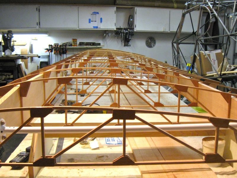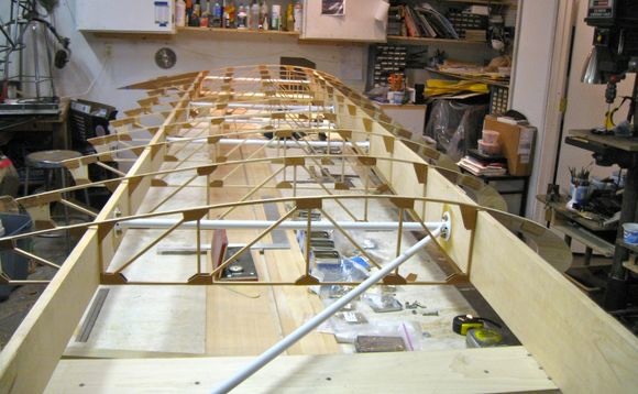
Over the last few months, I have made a lot of progress on the left wing. I have all the compression struts in place and I am ready to attach the drag – anti drag wires in preparation to square up the wing using a trammel. After the wing is square, each rib can then be glued in place. Although the compression struts took a lot more time than first thought (like everything else) I have all the parts and tools necessary to assemble the second wing; requiring a lot less time.
 Lets take a look at the finished compression struts. First one is the outboard most compression strut. I am building my wing with the traditional wood wing tip bow. This picture shows the outboard most ribs.
 The second compression strut includes the lift strut attach
fittings. This bay took the most time as I figured out the layout.
I had to re-make the “N” strut because of warping after welding. I did
not check alignment after welding and painted it. Had to start over.
I also found that the holes for the drag wire that passes through the smaller
tube in the “N” were drilled wrong by Wag. I had to weld up the holes and
re drill and re paint; very timely but live and learn.
The second compression strut includes the lift strut attach
fittings. This bay took the most time as I figured out the layout.
I had to re-make the “N” strut because of warping after welding. I did
not check alignment after welding and painted it. Had to start over.
I also found that the holes for the drag wire that passes through the smaller
tube in the “N” were drilled wrong by Wag. I had to weld up the holes and
re drill and re paint; very timely but live and learn.
 The third compression strut is the same as the first.
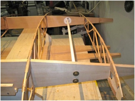
 This picture shows the tank bay with the cross brace installed. More detail below.
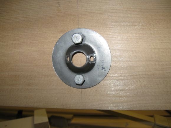
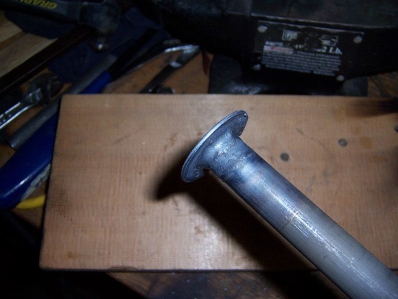 This is the first step in making the compression strut that goes between the wing attach fittings. Inside the tube I welded a nut than welded a washer on the outside. The plans did not show the washer welded in place, I chose to add that feature.
Next, rough fitting the cross brace to the tabs for proper fit.
 Here you can see the tab to attach the brace. I did not drill the brace for the right wing as that will have to be sized for the application.
I had to cut the washer to fit under the attach fitting. Not shown here but I will be using drilled head bolts for the compression strut and the hole above for safety wire.
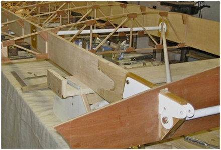 Here is the finished tank bay. I will need to move the
upright in the rib that rubs the cross brace.
Here is the finished tank bay. I will need to move the
upright in the rib that rubs the cross brace.
Next, the lift strut attach fittings needed washers welded to the bottom hole.
Here, the first paint job. Unfortunately, I had to weld up and drill the drag wire holes over so I had to paint these a second time.
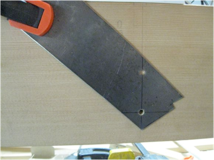 I used this piece of .090 with holes
the proper distance for the compression strut fittings. The line is used to align the holes as
needed for each fitting. Each fitting
needs to be individually marked and drilled to compensate for any
irregularities.
I used this piece of .090 with holes
the proper distance for the compression strut fittings. The line is used to align the holes as
needed for each fitting. Each fitting
needs to be individually marked and drilled to compensate for any
irregularities.
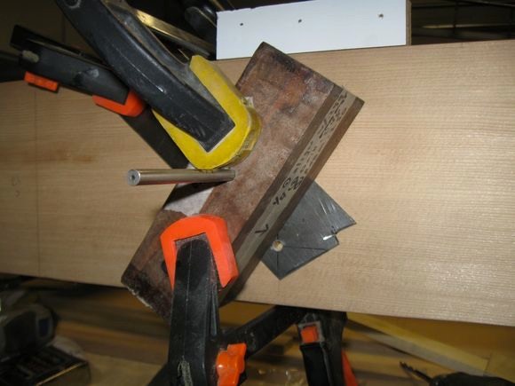
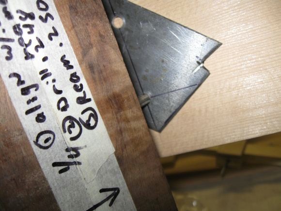 This picture
shows a piece of .090 I used to align the wood block for drilling. This
took some time at first but I got it figured out and it worked pretty well fore
each set of holes. I used a reamer for alignment than drilled the hole
undersized, finishing it off with the reamer. Worked great!
This picture
shows a piece of .090 I used to align the wood block for drilling. This
took some time at first but I got it figured out and it worked pretty well fore
each set of holes. I used a reamer for alignment than drilled the hole
undersized, finishing it off with the reamer. Worked great!
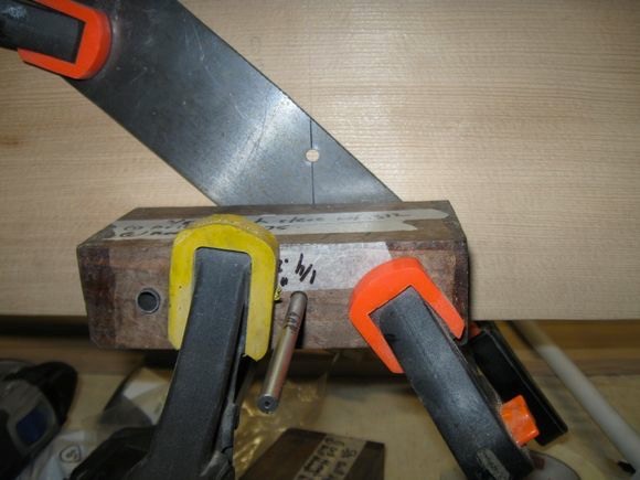 This is the drilling jig I used to drill all the holes in the spars. The holes needed to be drilled as the assemblies were added. Don’t pre-drill the holes. Even though I made a jig to weld the compression strut ends they weren’t perfect requiring each to be location to be drilled for an individual strut.
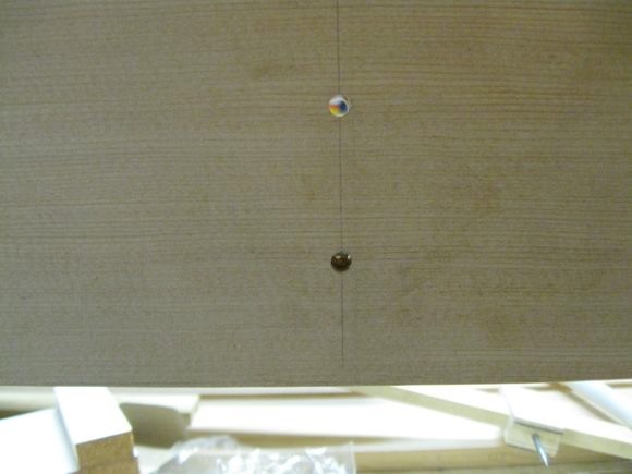
First hole done, ready for second hole. DO NOT move the steel plate between the holes. Second hole being aligned with the reamer prior to drilling. All holes were drilled the same way.
 Finished holes ……. repeat many times over.
Testing the hole alignment with an unused compression end fitting.
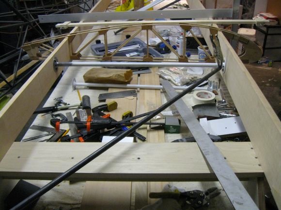
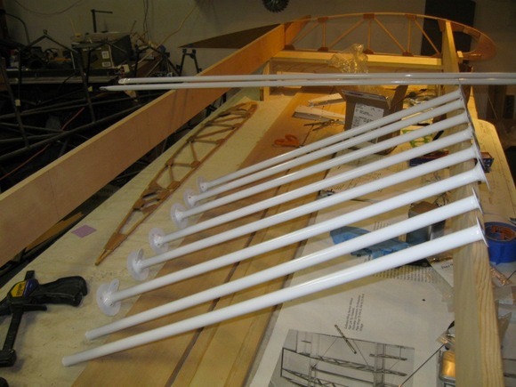 Here are all the compression struts and cross braces for both wings. Second wing should be much faster to assemble.
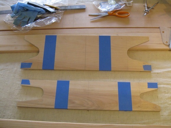 Next, cut and glue the plywood reinforcement that goes under the lift strut attach fittings. MAKE SURE you have all the ribs from the root end to this point in place because they will not fit over the ply after gluing. No, I did not make that mistake; I was warned before I started putting ribs in place!
 Glued in place, LOTS of clamps needed!!!
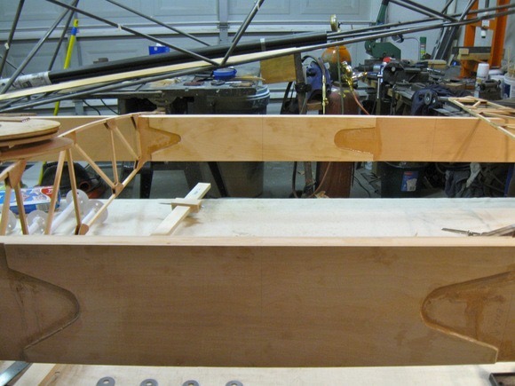
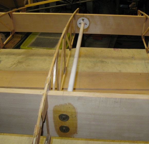
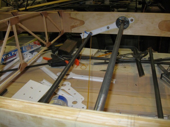
Finished and trimmed; ready for hole drilling and attaching the lift struts, drag wire, and the “N’ compression strut.
After I drilled and attached the lift strut attach fittings, I checked the fit of the drag wire. I didn’t realize the holes were in the wrong place and went ahead and fabricated and painted the complete “N” strut. Between warping during welding due to poor fit and the holes being off, I had to start over on the “N”. Not the first “do over”, and not the last I am sure.
So, lets start over. This is where I found out the holes were
wrong. The next pictures show the paint removed from the bottom of the
fittings due to the removal of the paint and welding and drilling of new
holes.
Here you can see the corrected fitting process. I used the Metal Geek
site to make the patterns for the fit of the diagonal tube. The angle
turned out to be 17 degrees and the paper patterns worked great.
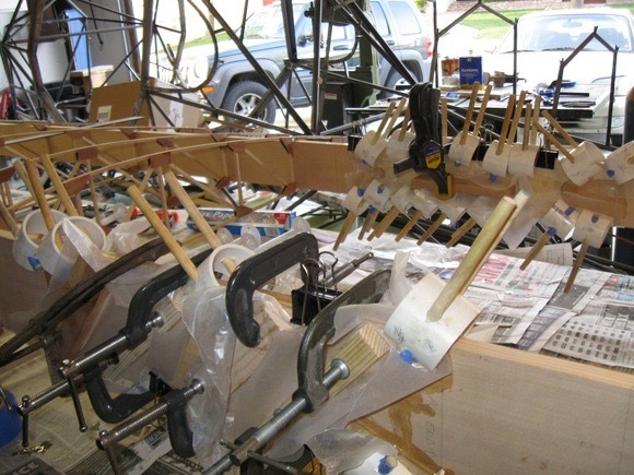
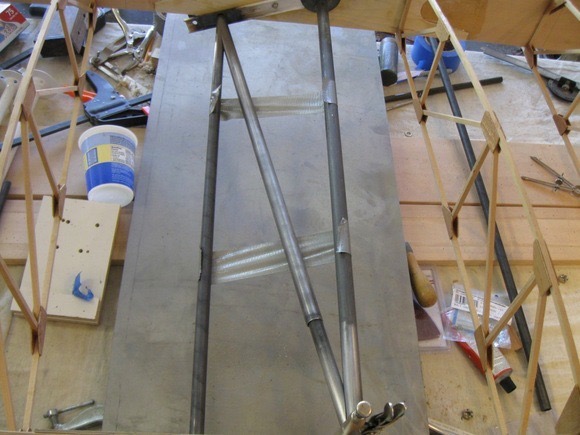 Tack welding
had to be done with everything bolted to the WOOD spars! Not for the
faint of heart. Work quick with a hot flame and you won’t have any
scorching. It was pretty easy and not to difficult. then weld,
install and make any necessary adjustments before painting.
Tack welding
had to be done with everything bolted to the WOOD spars! Not for the
faint of heart. Work quick with a hot flame and you won’t have any
scorching. It was pretty easy and not to difficult. then weld,
install and make any necessary adjustments before painting.
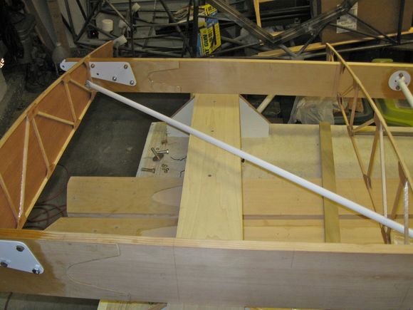
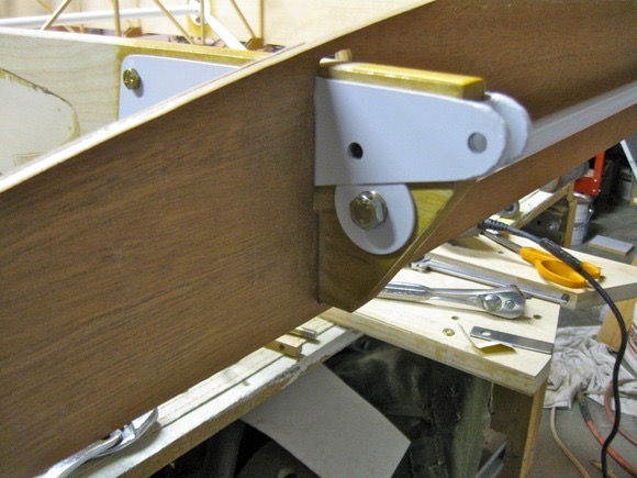
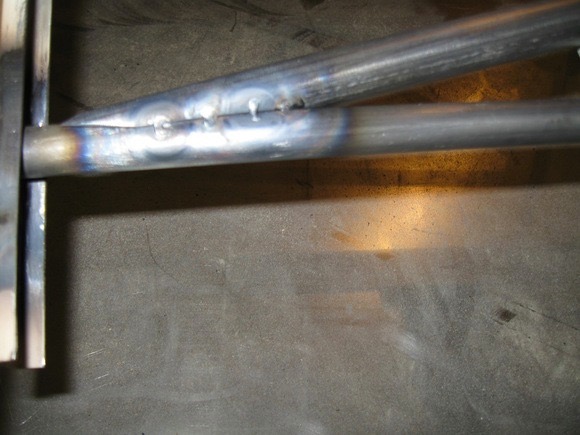 After welding
I did a last test fit. I needed to heat and slightly bend the tubes for
correct alignment. then, final paint.
After welding
I did a last test fit. I needed to heat and slightly bend the tubes for
correct alignment. then, final paint.
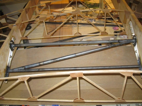
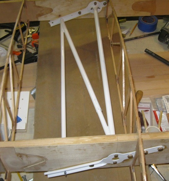
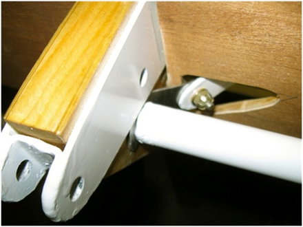
Painted and assembled in place.
Great fit …… sure took me some extra time!!!
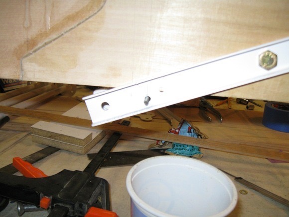
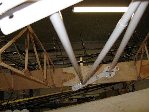 Here is a view from underneath to get a
better look at how it all goes together.
Here is a view from underneath to get a
better look at how it all goes together.