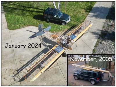

This entry shows the progress over the past three months or so. It may not look like much due to the “learning curve” on some of the parts. Needless to say, things took a lot longer to figure out than expected. As I began the process of building the stabilizer, I realized that I could make all the parts except the leading edge. The plans called for enlarging (swage) the end of the leading edge to fit over the connecting tube (tube between both stabs). Think tent poles. One tent pole is made larger to fit over the second tent pole of the same size. Seeing that there was no way to do this on my own and unable to find a formed leading edge with the swage, I redesigned the stab to use a sleeve rather than the swage. This was nothing new as I found at least one PMA’d part built the same way but no longer available.
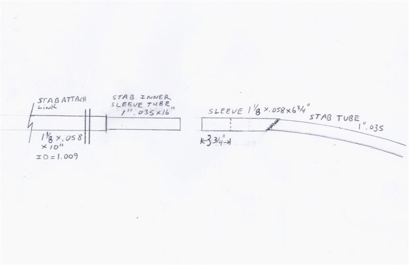 This is the design I came up with. I knew it required
making my own link assembly and connecting tube but the savings would be worth
it. Cost of PMA’d parts was about $ 250, my cost was about $15 plus lots
of time. So, I started on the link first. The link and horizontal stab re-design will eliminate need to swedge
end of tube.
This is the design I came up with. I knew it required
making my own link assembly and connecting tube but the savings would be worth
it. Cost of PMA’d parts was about $ 250, my cost was about $15 plus lots
of time. So, I started on the link first. The link and horizontal stab re-design will eliminate need to swedge
end of tube.
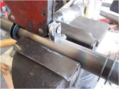
Most of the work was straight forward. The time came in keeping the inside of the link clean and straight to accept the connecting tube. I knew the connecting tube needed to be turned down and not having a lathe, that took time. I wound up grinding the connecting tube on a belt sander down to the proper diameter. I was able to get the tube + or – .003″ along the entire 16″ length so I was happy. The inside of the link assembly was sized using a brake cylinder hone going back and forth for a long time! All said and done, the link and connecting tube took me WAY too long but it came out great. By the way, some builders are using a polished or chromed connecting tube but Piper only calls for 4130 “fitted to a sliding fit” so I went with that. If you have a lathe to turn the connecting tube you will save lots of time. If you have a way to align bore the link, even better. Me, a brake hone with sand paper wrapped around it and lots of cutting oil did the trick. Did I mention LOTS of time?
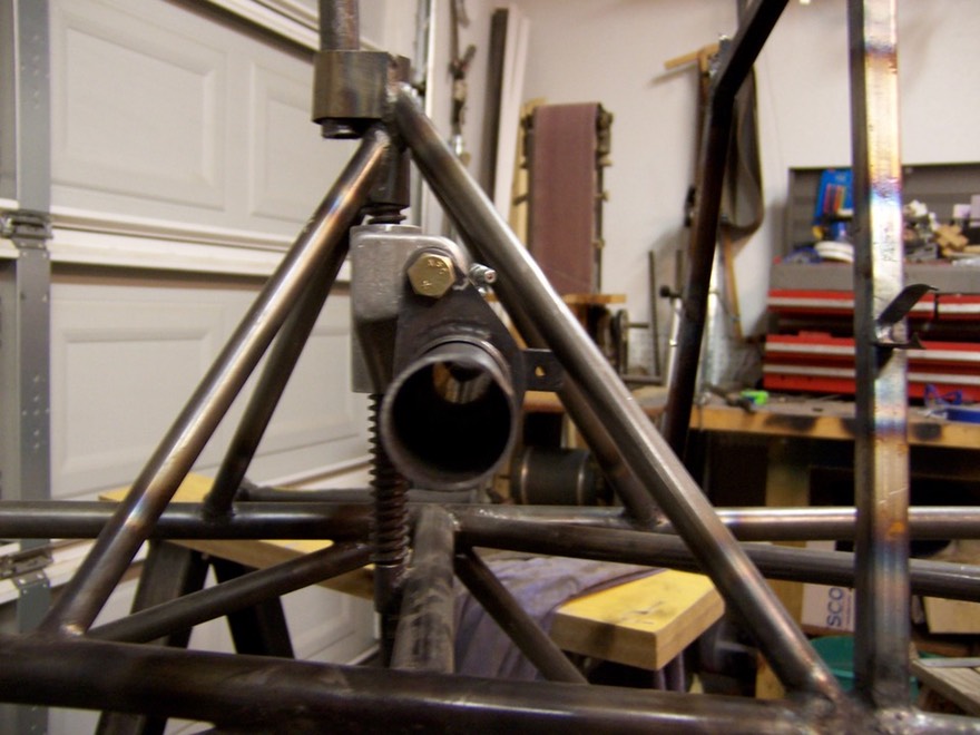
Building the link

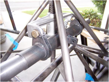
Another shot of the link
These little tabs are for the trim indicator wire.
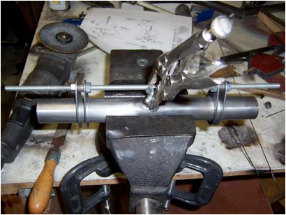
Finished link with connecting tube in place
Finished tube with stab connecting tub inside. Lots of honing was necessary to remove slag after welding all the tabs in place.
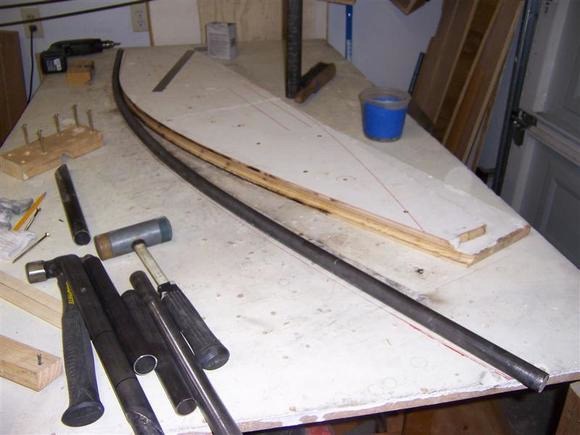
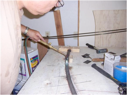
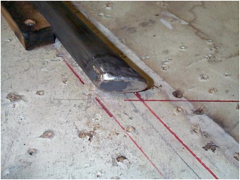
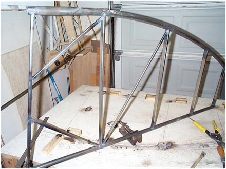
Next, bending the leading edge tube. I won’t show the mangled tubes that represented the learning curve. Lets just say that I spent about two weeks figuring this one out. Finally, another builder sent me a picture of his jig and it all worked out. My jig consisted of two pieces of 3/4″ ply cut to the curve with a “generous” amount of curve for spring back. I say generous because I had to adjust it three times to get it correct. I screwed them together andcut and sanded the profile. Then, I took them apart and used a 1/2″cove router bit on each piece, keeping in mind up and down, then screwed them back together now having a 1″ profile to match the tube. I packed the tube very tightly with sand and drove in wood plugs at bottom ends to keep tight. Most important thing about the bend is you MUST have a much longer piece of tube than necessary to make the bend work. 8′ is minimum length and 10′ would be better. You will wind up cutting off about 4′ when finished. This is another reason to use .035 rather than original .028. .035 is about $2.50 a foot and .028 is something like $8.25 a foot. .028 costs a lot more for the learning curve. With the end of the tube held tight against the end of the jig, slowly start pulling it into shape. You will need to move a bit of tube out past your starting end as you progress to get the curve just right. My first attempt had the sleeve welded in place. Big mistake. I had to redo those sleeves and weld on after the curve was bent. I did use a little bit of heat after I had the curve bent around the form to relieve a little stress. You will see in my pictures how much extra curve was needed to get everything just right. After three weeks and lots of figuring, the first tube was finished. The second one only took about 2 1/2 hours start to finish!
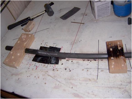
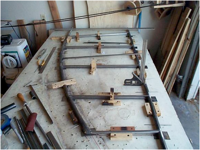
Tube clamped and bending begun. This doesn’t show additional block between the end one shown and tube. All tubes were packed with sand and capped at the ends with wood; compressing the sand inside. This helped prevent the tube from collapsing when being bent.
Here you can see the generous amount of curve needed on the jig for spring back. I had to extend the tube to about 9' to get enough leverage to make the bend. Slipping a larger pipe over the tube to b bent worked real well.
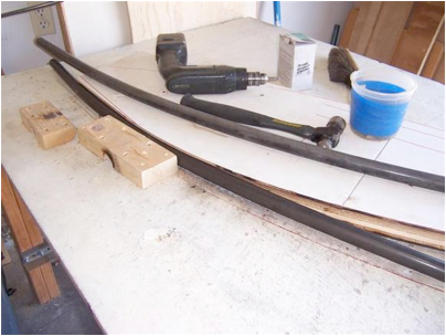
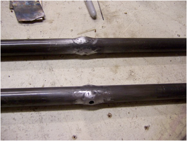
The second tube! Much faster
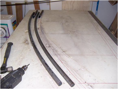
The two finished tubes with jig removed.
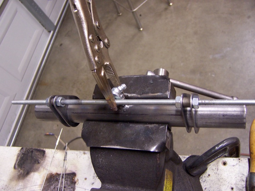
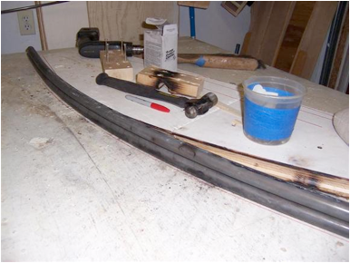
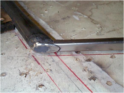
Next, I welded on the sleeves keeping the curve clamped in place.
I used a little heat to relieve any stress and let it cool to control spring back. I did this a few times until the curve was held with out any pressure.
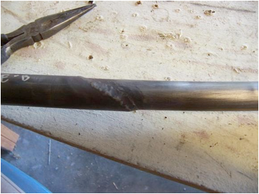
Finish weld of the sleeve. Now it was business as usual. The remainder of construction was the same as the rudder.
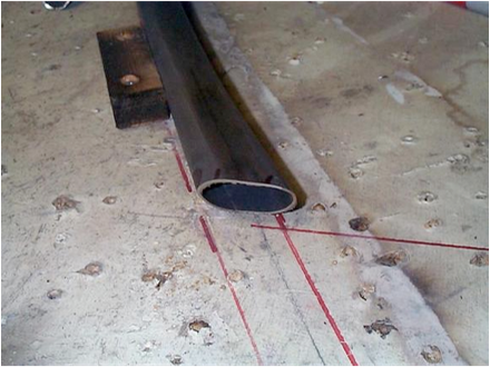
The plans did not show this step but it was on the Super Cub drawings so I did the same.
The plans did not show this step but it was on the Super Cub drawings so I did the same.
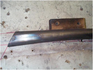
Here the end is welded closed
End rib fitted in place. All ribs were made in the same manner as the rudder ribs.
Trailing edge with bushings for tail brace wires
Ribs in place, ready for welding
The finished stab. For the second stab, repeat all the above steps without the learning curve!
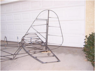
Here is everything after fit up. It is very important to keep the leading edge and the trailing edge exactly parallel with each other and the second stab exactly the same dimensions as the first for alignment. Mine were a little off and I had to cut the inside rib loose at one end, pull the tubes closer together and reweld. This was not the end of the world, just normal fitting as I see it. I have started on the elevators and have one of the curves bent but no pictures yet.