
The next step after all the tabs were welded in for seat belts was to build a rotisserie for the fuselage. This would be used for final welding, sandblasting, painting, assembly, and fabric work. I came up with a design that was cheap and fairly easy to build. I modified an engine stand from Harbor freight; making it taller and at a better angle for a fuselage. I needed the height to allow the vertical fin to clear the floor. I bought ($10) a drive shaft from a local junk yard, cut off one end and welded it to the stand. The U joint allowed the fuselage to rotate with binding if perfect alignment with rear stand was poor (it was). Rear stand was made from 4” x 4” lumber from the yard and some scrap steel welded and bolted where the tail wheel bolts to the fuselage. A couple of 2x4’s were used to connect the front stand with the rear. Both stands have wheels removed from Harbor Freight furniture dollies. Easy and cheap was the theme. I also fabricated a mount for the firewall attach points for the U joint to bolt to. Pictures should give a pretty good idea of how I built it. As for measurements; I have none. I just cobbled this together as I went along.
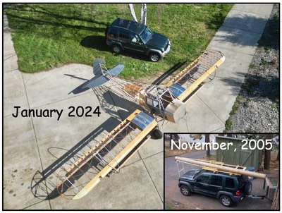
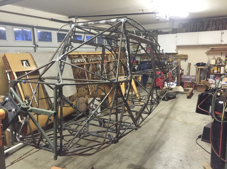
In this picture, you get an idea what I built. The two pieces of gray steel was bolted in place to get the height and angle needed for the front stand. The drive shaft was cut and welded to a steel plate than bolted to the engine stand rotating head. The opposite end of the U joint was bolted to the frame I made that attaches to the four points on the fuselage where the engine mount will bolt up.
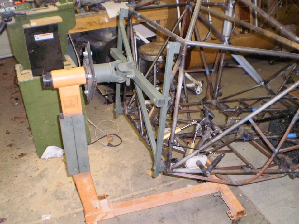
I didn’t get a good shot of the rear support so I’ll show some pictures from other steps that show the rear stand. This first one was outside when I was sandblasting. You can get an idea of how the stand looks; pretty easy.
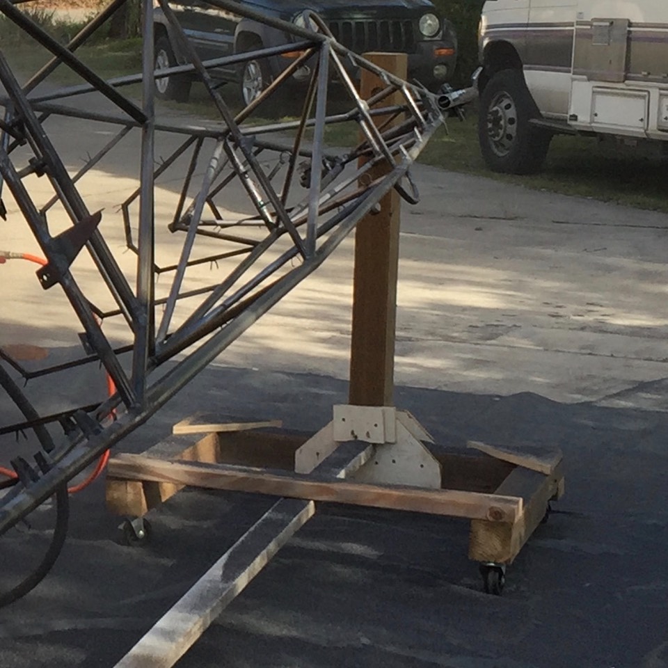
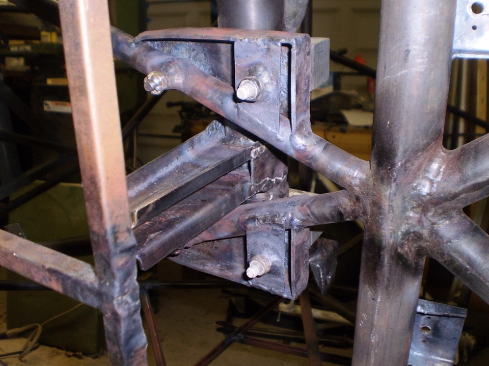
This next shot was after paint but it shows a pretty good view of the rear stand and how the fuselage bolts to the support pipe in the stand.
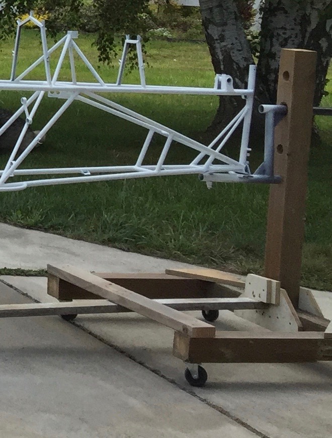
This next shot is out of sequence but shows the fuselage mounted in the stand. Only piece missing is the 2x4’s connecting front to back. Without the connecting piece, the fuselage could not be easily moved in the shop or outside to blast and paint.
With the stand built, it was time to finish up the welding. I had missed a step in welding up the mount for the control sticks and needed to weld in a missing bushing. This could not have been done with out being able to rotate the fuselage.
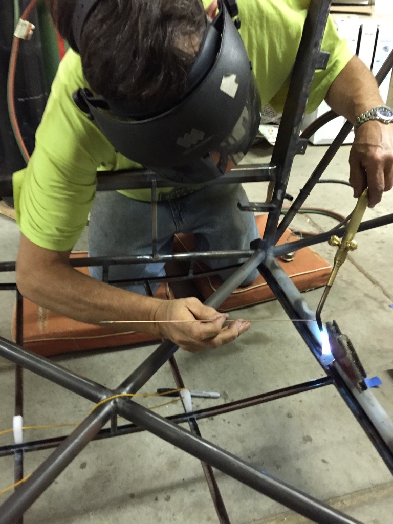
Other welding made easy. Here I was welding a tab to the upper front tube for the trim indicator wire to attach. Being able to rotate the fuselage is essential for this kind of welding.
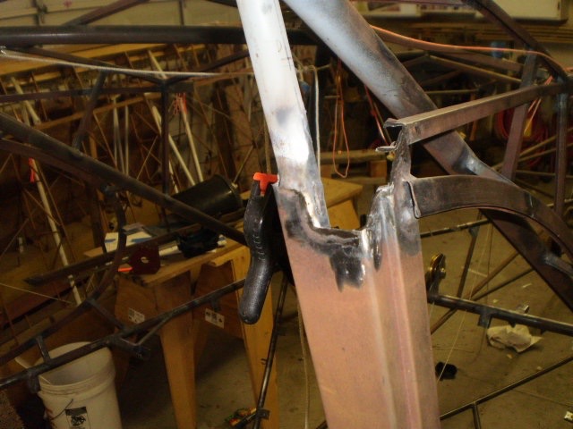
This is a shot of the bushings I needed to weld in place. I did not have the rear bushing; had to add that after being able to rotate the fuselage.
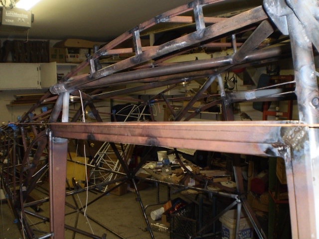
Another welding activity that was needed was a “repair”of the door openings. The top of the door openings were not the same distance from the bottom of the wing. About the same tine as I made the repair to the stick mount, I also removed and re-warded the top of the door opening’s sheet metal to be the same on both sides of the fuselage. I should have caught this when I attached my “short wings” that I use to build up the top deck. Live and learn. A couple shots of that step ……
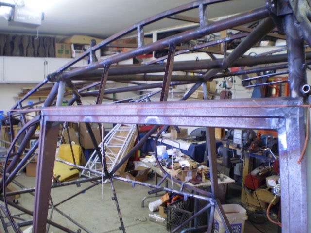
The top of the frame wasn’t parallel to the bottom of the wing. I found this out when I mounted my wings to weld in the cable pulleys. I would recommend welding the door frames after the wings can be mounted (or short wings) and proper measurements take. It took a bunch of time of fix both doors but well worth the effort.
Removed for re-welding
After the repairs were completed …….
About this same time, I welded in the electric trim mounting plate and tabs for metal belly sheetmetal. Enough for this post.
Return to Past Posts and Pictures by Date